![]()
It is recommended that you read the Head Timing Tab section before performing hook timing inspection/adjustment.
|
|
It is recommended that you read the Head Timing Tab section before performing hook timing inspection/adjustment. |
It is possible for the AMAYA rotary hook to slip from the factory-set hook timing. Inadequate timing between the hook and the needle can be one of the causes of upper thread breaks. The following inspection procedure will allow you to check the hook timing of your machine(s). If the hook timing position needs to be adjusted, follow the provided adjustment procedures.
|
Please note that you must have RSA 1.56 or higher installed to use this procedure to inspect/adjust hook timing. To check your RSA version, open the AMAYA OS Maintenance menu, then click the Information tab. (See the image to the right). If you do not have RSA 1.56 or higher, please contact the Melco Parts Department (phone #: 1-800-799-8313) to order the needed AMAYA OS software. |
|
Before making any hook timing changes, you need to perform an inspection to determine if adjustment is needed.
|
|
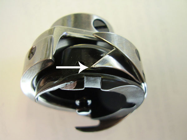
The procedures below refer to the part of the rotary hook called the "hook point." See the image below for the location of the hook point. |
Hex Wrench, 2mm
Hex Wrench, 2.5mm
Flat Blade Screwdriver
Magnifying Glass (Optional)
Flashlight (Optional)
Make sure your machine is turned on and AMAYA OS is running.
Engage the emergency stop button (by pushing it in).
Push the x-beam all the way to the back of the machine to ensure that the hoop arms will be out of the way during the procedure. (As an alternative to this, you could remove the hoop arms.)
Remove the needle plate, bobbin case, and rotary hook covers (using 2mm Hex wrench).
Disengage the emergency stop button (by twisting it).
You now need to determine the machine’s “closest needle.” The closest needle is defined as the needle that is closest to the hook basket needle guard and farthest from the hook point. The number of the closest needle is noted in the bottom right corner of the machine casting (under the black base cover). Lift the base cover, then make a note of the closest needle (the closest needle number is identified as C-X, where X is the needle number). You also need to note the z-axis position (measured in degrees) that is written in the same location. See the image below for the locations of these two numbers on the machine casting.
NOTE: If there is not a z axis position written on the machine casting, use 197° for the z position. If there is not a closest needle written,
click here.
Replace the base cover.
The first inspection will be to check the clearance between the back surface of the needle and the hook basket (also called the bobbin case holder) needle guard. This clearance is referred to as the needle guard gap.
Open the Maintenance menu and then click the Head Timing tab.
In the Head Timing tab, click the Head Up button (or on the AMAYA keypad, press the Adjustment key ![]() and the Up Arrow key).
and the Up Arrow key).
Use the AMAYA keypad to move the needle case (![]() +
+ ![]() or
or ![]() ) to the closest needle noted in the machine casting.
) to the closest needle noted in the machine casting.
If the needle is bent or damaged, replace the needle (click here for instructions on replacing the needle).
When checking the needle guard gap, the eye of the closest needle must be facing directly forward or be turned to the right by a maximum of 10°. Click here for instructions on changing needle orientation.
In the Head Timing tab, click the Head Up button, then the Bottom Center button (or on the AMAYA keypad, press the Adjustment key ![]() and the Up Arrow key to go to Head Up, then press the Adjustment key and the Down Arrow key to go to Bottom Center.)
and the Up Arrow key to go to Head Up, then press the Adjustment key and the Down Arrow key to go to Bottom Center.)
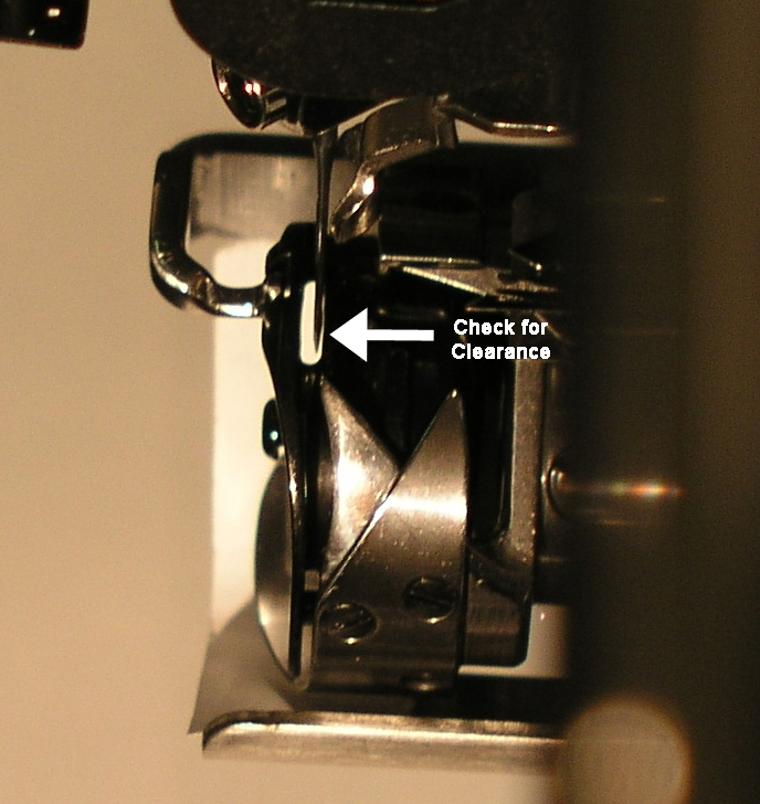
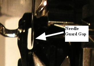
Using the following image as a guide, examine the area between the back surface of the needle and the hook basket needle guard (the needle guard gap). (You may find a magnifying glass and a flashlight useful when doing this). There should be a small amount of clearance in this area. That is, the back surface of the needle should not be touching the hook basket needle guard. The following image displays the ideal needle guard gap (which is approximately 0.001”/0.025mm). If the back surface of the needle is touching the hook basket needle guard, or if the gap is too wide, the hook position will need to be adjusted.
You can now inspect the hook timing, which refers to the rotational position of the hook point in relation to the needle. To check the hook timing, stand directly in front of the machine, then locate the needle. The hook point should be just barely visible on the left side of the needle. Use the image below to locate the hook point behind the needle (it may be helpful to use a magnifying glass to see this).
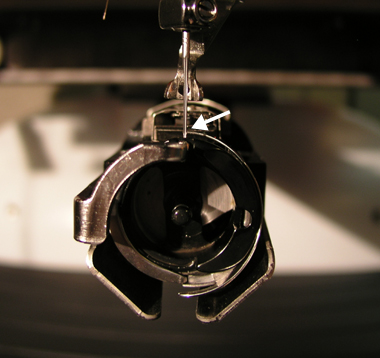
The optimal hook point position is displayed in the image above (the hook point should be just barely visible on the left side of the needle). However, a rotational position within a small range is acceptable. This range falls between the alignment of the left edge of the hook point with the left edge of the needle, and the alignment of the left edge of the hook point with the right edge of the needle (the following image displays this range). If the hook point position does not fall within this acceptable range, you need to perform hook timing adjustment.
Optimal Position
Left Hook Point Edge aligned with Right Edge of Needle
If desired, (it is not required), you can now inspect the needle to hook gap (front to back position of the rotary hook).
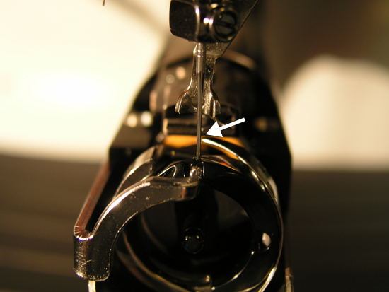
The needle to hook gap refers to the gap between the hook point and the needle scarf. To check this gap, stand on the right side of the machine, then look behind the needle. You should see the hook point directly behind the needle scarf (it may be helpful to use a magnifying glass to do this). The space between the needle scarf and the hook point is the needle to hook gap. Use the following image to locate the gap.
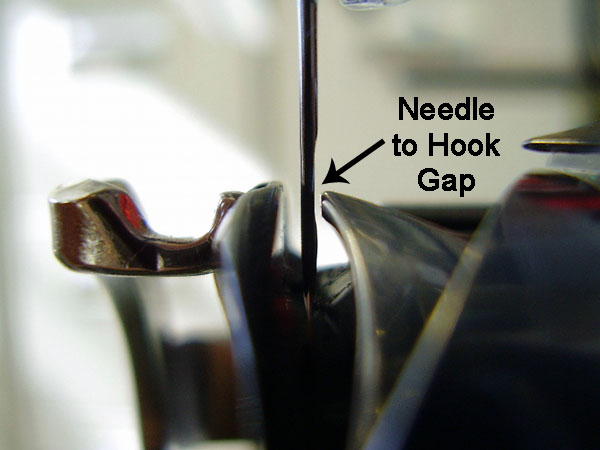
Once you have located the needle to hook gap, you can check the gap width. The width of the gap should be between 0.004 and 0.012 inches / 0.10 and 0.30mm (approximately 1-3 thread widths). As a guide, the image above displays the correct needle to hook gap width.
If the needle guard gap or the rotational hook timing are not correct, proceed to the next section to perform hook timing adjustment.
You will first adjust the needle guard gap.
Open the Maintenance menu and then click the Head Timing tab. Click the Head Up button (or on the AMAYA keypad, press the Adjustment key ![]() and the Up Arrow key).
and the Up Arrow key).
Use the AMAYA keypad to move the needle case (![]() +
+ ![]() or
or ![]() ) to the needle noted in the machine casting.
) to the needle noted in the machine casting.
If the needle is bent or damaged, replace the needle (click here for instructions on replacing the needle).
When adjusting the needle guard gap, the eye of the closest needle must be facing directly forward or be turned to the right by a maximum of 10°. Click here for instructions on changing needle orientation.
On the AMAYA keypad, use the hook rotation function (press and hold the Adjustment key ![]() , then press the Right Arrow key
, then press the Right Arrow key ![]() ) until one of the two screws on the curved side of the rotary hook is exposed on the right side of the needle plate bracket. (See image below).
) until one of the two screws on the curved side of the rotary hook is exposed on the right side of the needle plate bracket. (See image below).
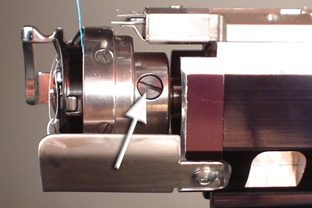
Using a flat blade screwdriver, slightly loosen (do not remove) the exposed screw. Then re-tighten the screw just enough so that the hook will hold its position when rotated, but can still be moved with your fingers.
Press and hold the Adjustment key ![]() , then press the Right Arrow key
, then press the Right Arrow key ![]() until the other screw on the curved side of the rotary hook is exposed. Slightly loosen (do not remove) that screw. Then re-tighten the screw just enough so that the hook will hold its position when rotated, but can still be moved with your fingers.
until the other screw on the curved side of the rotary hook is exposed. Slightly loosen (do not remove) that screw. Then re-tighten the screw just enough so that the hook will hold its position when rotated, but can still be moved with your fingers.
In the Head Timing tab, click the Head Up button, then click the Bottom Center button (or on the AMAYA keypad, press the Adjustment key ![]() and the Up Arrow key to go to Head Up, then press the Adjustment key and the Down Arrow key to go to Bottom Center.)
and the Up Arrow key to go to Head Up, then press the Adjustment key and the Down Arrow key to go to Bottom Center.)
In the Head Timing tab, click the Hook Timing button (or on the AMAYA keypad, press the Adjustment key ![]() and the Right Arrow key). This will expose the screw on the flat side of the rotary hook.
and the Right Arrow key). This will expose the screw on the flat side of the rotary hook.
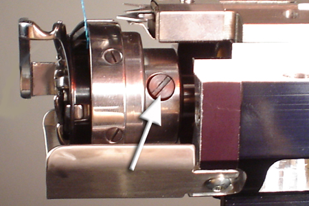
First slightly loosen (do not remove) this screw. Then re-tighten the screw just enough so that the hook will hold its position when rotated, but can still be moved with your fingers.
In the Head Timing tab, click the Head Up button, then click the Bottom Center button (or on the AMAYA keypad, press the Adjustment key ![]() and the Up Arrow key to go to Head Up, then press the Adjustment key and the Down Arrow key to go to Bottom Center.)
and the Up Arrow key to go to Head Up, then press the Adjustment key and the Down Arrow key to go to Bottom Center.)
Move the hook to the correct position to obtain the correct needle guard gap (between the hook basket needle guard and the back surface of the needle). You may find a magnifying glass and a flashlight useful when doing this. The back surface of the needle should not be touching the hook basket needle guard. The needle guard gap should be approximately 0.001”/0.025mm. See the following image.
Slightly tighten the rotary hook screw that is exposed on the right side of the lower arm extension.
You now need to take the machine to the z-axis position written on the machine casting (or to 197 if there was no z axis position written on the machine casting).
If the z-axis position written on the machine casting is a whole number (e.g., 200), use the Set Position box and the Goto Position button to move the machine to that z-axis position. To do this, enter the number in the Set Position box, then click the Goto Position button. Check the number displayed in the Current Z Position box (see image below). This number may not be the exact number you entered. If it is not, use the microstep forward command on the keypad (press and hold the press and hold the Trace key ![]() , then press the Up Arrow button
, then press the Up Arrow button ![]() ) to increase the z position by tenths (of degrees) until the correct z-axis position is displayed in the Current Z Position box.
) to increase the z position by tenths (of degrees) until the correct z-axis position is displayed in the Current Z Position box.
NOTE: If you microstep too far, repeat steps 11 and 14. Do not microstep backward.

If the z-axis position written on the machine casting is not a whole number (e.g., 200.2), round down at least one degree to the nearest whole number (e.g., you should round 200.2 down to 199) and enter the whole number in the Set Position box, then click the Goto Position button. Then, use the microstep forward command on the keypad (press and hold the press and hold the Trace key ![]() , then press the Up Arrow button
, then press the Up Arrow button ![]() ) to increase the z position by tenths (of degrees) until the correct z-axis position is displayed in the Current Z Position box.
) to increase the z position by tenths (of degrees) until the correct z-axis position is displayed in the Current Z Position box.
NOTE: If you microstep too far, repeat steps 11 and 14. Do not microstep backward.
You can now adjust the hook timing, using the following image as a guide. Even if hook timing was correct during the inspection process, you should check it again during the adjustment process, because you will be moving the hook.
To set the hook timing rotationally, align the hook point to the approximate hook timing position as shown in the following image. (The following image reflects the view of the needle and hook point when looking from the front of the machine).
Remember the optimal position is such that the hook point is just barely visible on the left side of the needle, but a rotational position within a small range is acceptable. This range falls between the alignment of the left edge of the hook point with the left edge of the needle, and the alignment of the left edge of the hook point with the right edge of the needle (click here to view an image that displays this range).
Please note that it is not uncommon to repeat the adjustment several times to obtain the correct hook timing.
Slightly tighten the screw on the flat side of the rotary hook, being careful not to move the hook position.
NOTE: While adjusting the needle to hook gap and/or hook timing, you should periodically make sure that the z axis position has not changed (check the Current Z Position box). If the z position has changed, repeat steps 11 and 14-16 of this procedure; make sure the screw on the flat side of the rotary hook is tightened).
In the Head Timing tab, click the Head Up button, then click the Bottom Center button (or on the AMAYA keypad, press the Adjustment key ![]() and the Up Arrow key to go to Head Up, then press the Adjustment key and the Down Arrow key to go to Bottom Center.)
and the Up Arrow key to go to Head Up, then press the Adjustment key and the Down Arrow key to go to Bottom Center.)
Verify that the needle guard gap is still correct. If it is not, repeat the needle guard gap adjustment.
Repeat step 14, then verify that the rotational hook timing is still correct. If it is not, repeat the rotational hook timing adjustment.
Once you have verified that both the needle guard gap and the rotational hook timing are correct, use the hook rotation function (press and hold the Adjustment key ![]() , then press the Right Arrow key
, then press the Right Arrow key ![]() ) to rotate the hook all the way around one time. As each of the three screws is exposed, slightly tighten each screw.
) to rotate the hook all the way around one time. As each of the three screws is exposed, slightly tighten each screw.
Repeat step 20 to rotate the hook all the way around again. This time, completely tighten each screw as it is exposed.
Repeat steps 17-19 to verify that the needle guard gap and rotational hook timing are still correct.
In the Head Timing tab, click the Head Up button, then click the Bottom Center button (or on the AMAYA keypad, press the Adjustment key ![]() and the Up Arrow key to go to Head Up, then press the Adjustment key and the Down Arrow key to go to Bottom Center.)
and the Up Arrow key to go to Head Up, then press the Adjustment key and the Down Arrow key to go to Bottom Center.)
Refer to the Rotary Hook Support Adjustment chapter to finish adjusting the rotary hook.
![]()