![]()
The rotary hook support may need to be adjusted if a garment gets caught in the rotary hook, or if it is loosened. The proper adjustment of the rotary hook support is based on proper needle case calibration, please refer to the Needle Case Calibration procedure if necessary prior to completing the inspection.
Tools Needed:
Hook Retaining Finger Gauge (PN: 009027-01) Thickness = 0.020”. Tolerance = 0.002”
2mm Allen Wrench
2.5mm Allen Wrench for the needle plate.
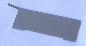
Figure 1 - Hook Retaining Finger Gauge
Remove the bobbin case.
Remove the needle plate.
a. Remove the 2.5mm Allen screws that secure the needle plate.
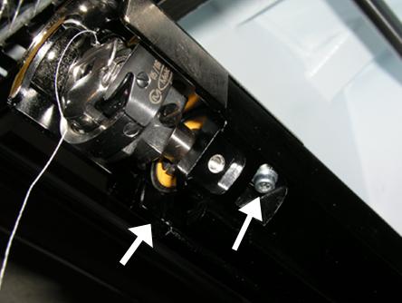
Figure 2 – Needle Plate Screws
In AOS, click on Maintenance Menu and then click the Head Timing Tab.
Click the button labeled Bottom Center.
CAUTION: The needle will move without any on-screen prompting when you are in the Maintenance Menu.
Figure 3 – Head Timing Tab
Inspect the left-to-right position of the tip of the hook support (the portion of the hook support that is positioned inside the notch of the rotary hook – see Fig. 5) as it aligns to the needle. It should be centered left-to-right. If not, it may be necessary to bend the hook support to the correct alignment by hand (without tools), being careful not to scratch the highly polished surface. If this is not possible, you may need to replace the hook support (PN: 33046).
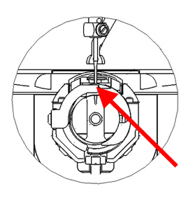
Figure 4 – Hook Support Position Left-to-Right
Once the left-to-right position of the hook support is correct, click the Head Up button and then click OK.
Insert the retaining finger gauge between the hook support and the hook basket.
CAUTION: If the gauge does not slide in easily, do not force it. You may scratch the highly polished surface of the hook support or hook basket, resulting in thread breaks.
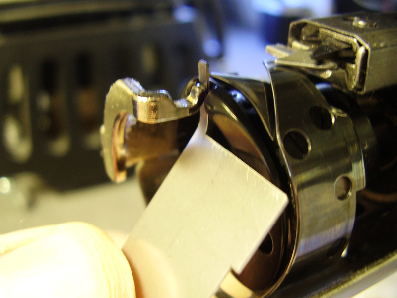
Figure 5 – Retaining Finger Gauge Usage
The retaining finger gauge should slide between the hook support and hook basket with no resistance. The gap between the hook support and hook basket should be no more than 1.1 times the thickness of the gauge. (The gauge is 0.020” and the tolerance is +/- 0.002”.)
The tip of the hook support should be flush with the top of the hook basket.
If the adjustment is not correct, continue to the Adjustment Procedure below.
Note: Prior to adjustment, be sure to follow steps 1 through 9 in the Rotary Hook Support Inspection Procedure above.
Use the 2mm Allen wrench to loosen the 2 screws holding the hook support.
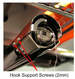
Figure 1 – Hook Support Screws
Position the hook support in the notch at the top of the rotary hook basket.
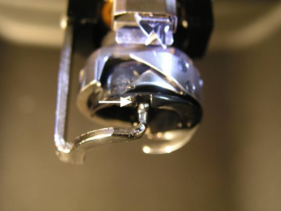
Figure 2 – Rotary Hook Basket Notch
Insert the gauge between the hook support and hook basket.
Holding the hook support from the side with the adjustment screws, adjust the position of the hook support to the requirements specified in the inspection procedure.
Remove the gauge while holding the position of the hook support, being careful not to scratch the highly polished surface (this is critical to proper operation).
Tighten the 2 screws holding the hook support.
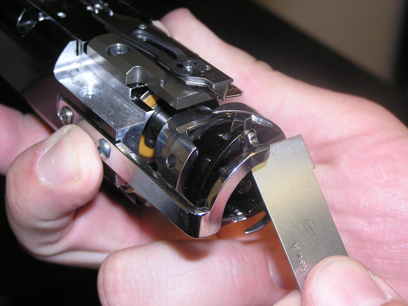
Figure 3 – Hook Support Adjustment
Verify that the gauge still slides freely between the basket and hook support.
You may now reinstall the needle plate and bobbin case.