![]()
The grabber/threadfeed/cc home harness connects the grabber home PCB and the threadfeed/cc home PCB to the Main PCB at connector location J31.
Replacement Parts Needed:
harness, grabber/threadfeed/cc home
Twist Lock cable ties (available at most hardware stores in the electrical section)
Replacement Procedures:
1. Turn the machine OFF.
2. Color change to Needle 1. (To allow access to both home PCBs)
3. Remove the right transparent arm cover and the back screw of the left.
|
|
CAUTION!! Use extreme care not to drop metallic objects, tools, or other conductive material on the Main PCB when you have the base cover removed. If you drop such objects on the Main PCB, it can severely damage the electronics which will be very expensive to repair. |
4. Remove the base cover, upper arm back cover and the lower arm rear cover.
5. Remove any twist-lock cable ties that bundle the grabber/threadfeed/cc harness to adjacent ones behind the needle case assembly and any cable ties that tie the connectors to the PCBs. Set them aside for re-use.
Figure 1 - Grabber Home Harness Lead
6. Disconnect the grabber/threadfeed/cc harness from the grabber home PCB located at the top left behind the needlecase. The grabber/threadfeed/cc harness lead is the four pin connector. The five pin connector is the grabber stepper motor interface cable.
Figure 2 - Thread Feeder Home PCB
7. Disconnect the grabber/threadfeed/cc harness from the thread feeder home PCB located at the top center right behind the needlecase assembly (on the right above the thread feeder stepper motor). The grabber/threadfeed/cc harness threadfeed home lead is the four pin connector identified in Figure 2 above. The five pin connector is for the stepper motor interface cable.
8. Remove any twist-lock cable ties bundling the harnesses together behind the thread tree base and pull the grabber/threadfeed/cc harness from under the thread tree base all the way to the back down to the right lower arm access hole.
|
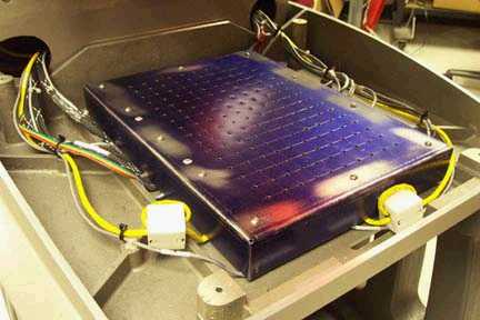
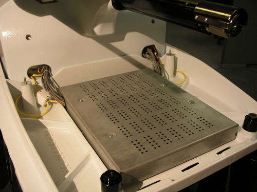
Figure 3a - 32188 Series EMI Cover |
Figure 3b - 32232 Series EMI Cover |
9. Remove the EMI cover from the main control board by removing the screws from the edge of the cover.

Figure 4 - Grabber/Threadfeed/CC Harness Connection at Main PCB
10. Disconnect the grabber/threadfeed/cc harness from the main PCB at connector location J31 and remove any twist-lock cable ties bundling the harnesses together in the base area and remove the harness.
11. Connect the replacement grabber/threadfeed/cc harness leads to the grabber home PCB and threadfeed home PCB as appropriate. The leads are marked "GRABBER HOME/CC POSITION" and "THREAD FEED/CC HOME" respectively to indicate where they are to be connected.
12. Insert the other end of the harness underneath the thread tree base and pull it through from the rear and leave it hanging loose. Provide about 14" length on the grabber/threadfeed/cc harness connector. This end of the harness will travel with the needlecase assembly as it moves left and right.
13. Tie the harness connectors to the PCB with cable ties to prevent them from coming loose during machine operation. Position cable ties between the harness wires on the center of the connector.
14. Run the grabber/threadfeed/cc harness along the same path as the adjacent harnesses, bundling them together with twist-lock cable ties. Add another twist-lock cable tie where they meet together in the right wiring channel of the upper arm.
15. Run the cable through the right wiring channel, down to the right lower arm access hole to the PCB and connect it to the Main PCB at connector location J31.
16. Tie the adjacent harnesses together with the grabber/threadfeed/cc harness with cable ties at about 3-4 inch intervals.
17. Replace the EMI Cover carefully following the instructions provided in "EMI Cover - 32232 Series" or EMI Cover - 32188 Series" as appropriate (see Figures 3a and 3b for pictures).
18. Install the covers in the reverse order that you removed them and tighten the screws to Melco Torque Specifications.
19. Run a short machine functional test and verify that the grabber, thread feeder, and color change functions are working properly.
![]()