![]()
Beginning with serial number 320500 series, most machines will have the EMI cover assembly (PN: 32232) installed. Older machines will have the old type EMI covers (PN: 32188) installed. Due to problems with the harnesses being damaged when the cover is not carefully installed, it is recommended that the old type covers be replaced as the machine is serviced in the field, or when damaged harnesses are found (damaged from being bent underneath the old style covers).
Removal of the EMI Cover:
1. Engage the emergency stop by pressing ![]() in or turn the machine OFF.
in or turn the machine OFF.
2. Carefully remove the screws, being careful not to strip them. Break them loose first. Set the screws aside where they can not be dropped accidentally onto the main PCB underneath the EMI Cover.
3. Remove the cover.
|
|
CAUTION!! Use extreme care not to drop metallic objects, tools, or other conductive material on the Main PCB when you have the base cover removed. If you drop such objects on the Main PCB, it can severely damage the electronics which will be very expensive to repair. |
Installation of new type EMI Cover:
|
|
CAUTION!! Use extreme care not to damage the Main PCB during the installation of the EMI cover. Do not put stress on the harness connections or the harnesses. Avoid sharp bends in the harnesses as that may damage the harness beyond repair. Failure to exercise this caution during installation of the EMI cover can result in severe damage to the Main PCB and will be very expensive to repair. |
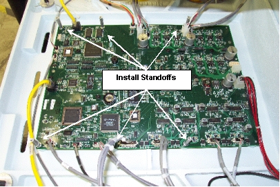
Figure 1 - Standoff Installation Pattern
Install six M4x6mm hex standoffs ( PN: 32193-13) with M4 flat washers (PN: 690439-04) into position on the main PCB as shown in Figure 1 above. Tighten the standoffs only to finger tight or you might break them off in the casting.
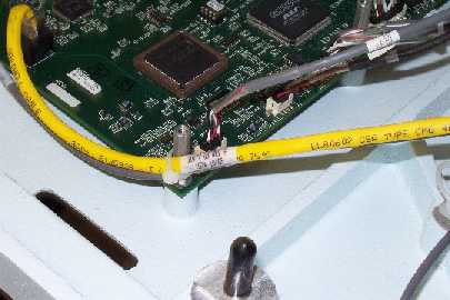
Figure 2 - Tie User Interface and Right LED Cluster Harness to Standoff
Remove the ferrite block from the user interface harness.
Gather and tie the user interface and the right LED cluster harness to the front right standoff as shown in Figure 2 above.
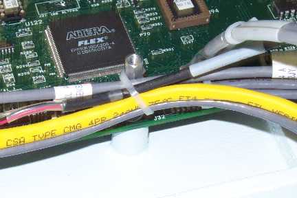
Figure 3 - Gather Harnesses and Tie to Middle Standoffs
Gather the user interface and right hand harnesses and bundle them with the adjacent harnesses and tie them to the second and third standoffs on the right hand side of the Main PCB as shown in Figure 3 above.
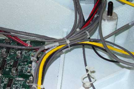
Figure 4 - Cable Tie Right and Back Harnesses together.
Pull the remaining slack from all of the harnesses coming from the right and back sides and tie them with a cable tie as shown in Figure 4 above.
Pull excess slack from the back and right harnesses into the right casting access hole and leave the loose slack inside the rear cavity of the bottom casting.
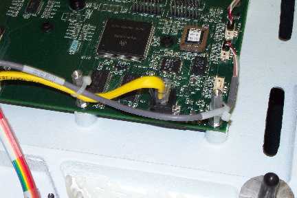
Figure 5 - Cable Tie Harnesses to Left Front and Left Side Standoffs
Remove the ferrite block from the Ethernet harness.
Pull the slack from the left LED cluster harness and tie it to the left front standoff as shown in Figure 5 above.
Gather the LED Cluster and the Ethernet harness together and tie it to the second standoff on the left side of the PCB.
Gather the LED Cluster and the adjacent harnesses and tie it to the third standoff on the left side of the PCB just as you did on the right side.
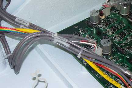
Figure 6 - Cable Tie Harnesses at Left Rear of Main PCB
Pull the remaining slack out of the left harnesses and tie them as shown in Figure 6 above.
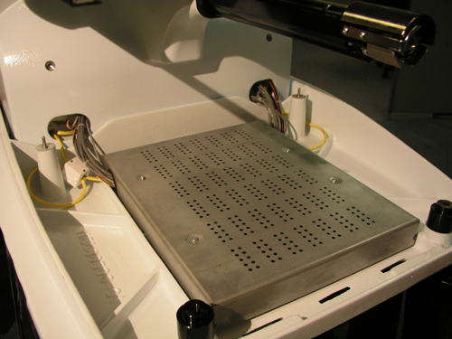
Figure 7 - EMI Cover (new type) Installed
Install the EMI cover (new style) (PN: 32232) using four M4x8mm pan head Phillips screws w/star (PN: 009863-08). Tighten the screws to Melco Torque Specifications.
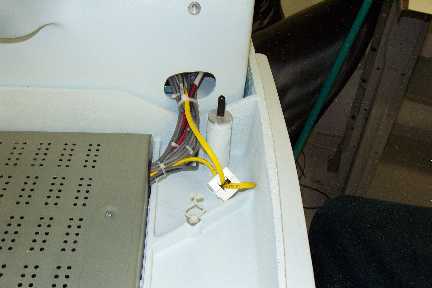
Figure 8 - Ferrite Block Installation and Cable Ties at Right Side of Cover
Install the ferrite block back onto the user interface harness and tie the harnesses together as shown in Figure 8 above, pushing excess slack into the back cavity of the lower arm casting.
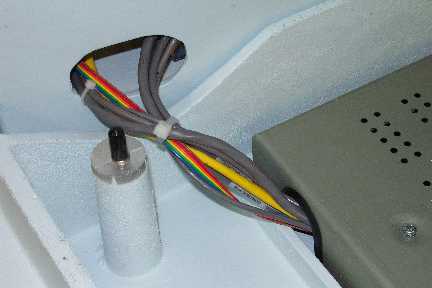
Figure 9 - Harness Tied at Left Side of EMI Cover
Tie the harnesses on the left side of the EMI cover together as shown in Figure 9 above, pushing excess slack into the back cavity of the lower arm casting.
You may either remove the four press-in type cable clamps (PN: 30788) or leave them in place. They are no longer needed. At the factory, they are no longer installed under the bed cover.
Install the bed cover.
![]()