![]()
|
Figure 1 |
Figure 2 |
Figure 3 |
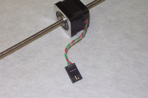
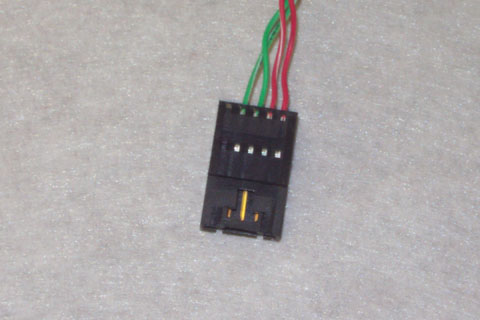
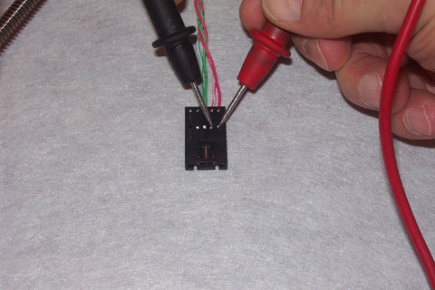
Resistance in the stepper motors is measured on the two phases. To measure the resistance, disconnect the motor at the connectors (see Figure 1). There are four wires to each motor. Starting from either side, the first two wires are one phase and the remaining two wires are the second phase. At the connector, you can see tabs where the pins are (see Figure 2 and Figure 3). These can be used to measure the resistance. Each motor, regardless of the connector, can be measured this way.
|
|
IMPORTANT: Set the multimeter to the ohm scale and zero it out by touching the two leads together and pressing the appropriate button to zero your meter (see your meter instruction manual on how to do this). If you do not know how to zero your meter, take note of the resistance measured when the two leads are touched together and subtract that from the actual measurement. This gives you the true resistance measurement. |
Measure the resistance of the windings. The readings should be about 10-14% of the following values:
|
Color Change Motor |
7.3 ohms |
|
Grabber Motor |
25 ohms |
|
Thread Feed Motor |
25 ohms |
|
Trimmer Motor |
25 ohms |
A low measurement indicates the motor has a shorted winding. A high measurement indicates the motor has an open winding. In either case, the motor should be replaced.
![]()