![]()
|
|
This repair requires timing and other adjustments and should be done by a Melco authorized service technician. |
When installing the x-drive cable it is extremely important that you do not damage the protective coating of the cable, ensure that the windings on the cable spool are correct, that the cable is correctly tensioned, and the installation is done precisely as provided in these instructions.
When replacing the x-drive cable it is strongly recommended that the x-drive cable assembly be ordered and installed. The precision windings and lengths of the cable extending from the spool is critical and is best done only at the factory.
|
|
CAUTION!! Use extreme care to avoid damaging the protective coating on the x-drive cable. If the coating is damaged, the cable will eventually fray and/or corrode. |
|
|
CAUTION!! At any time when the machine is either powered down or in E-Stop mode, neither the X-Carriage nor the X-Beam should be moved at a high rate of speed. If there is a desire to manually move either the carriage or the beam, they should be pushed or pulled GENTLY to prevent serious damage to the main control board. |
Replacement Parts Needed:
x-cable assembly (x-cable prewound on spool)
Order other replacement parts if needed, such as pulleys
Replacement hardware if any screws or nuts are stripped
X-Cable Assembly Installation:
1. Remove left and right transparent arm covers.
2. Remove the upper arm back cover.
3. Remove the old x-drive cable assembly.
4. Make sure the x-carriage is positioned all the way to the right (as seen from the back of the machine) at a hard stop.
5. Verify the 8mm bushing is installed on the X-motor shaft.
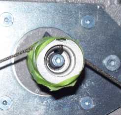
Figure 1 - X-Cable Spool
(Taped and Installed)
|
|
CAUTION!! DO NOT remove the tape from the x-cable spool when you install it until the cables are tightened up. The cable will become unwound and will be extremely difficult to rewind with the precise lengths needed to install it on the machine. |
6. Install the x-cable spool assembly on the x-motor shaft with an 8mm bushing, 5/16IDx .031 THK shaft spacer, four 8mmIDx18mmOD external star washers, one .173IDx.375OD D-Shaped washer, and one M4x10mm cap head socket screw. Tighten the screw to 11 in-lbs (1.2Nm) of torque.
|
|
The four external washers are already inside the X-Cable spool assembly. Handle with care to prevent the washers from falling out. |
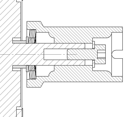
Figure 2 - Assembly Drawing
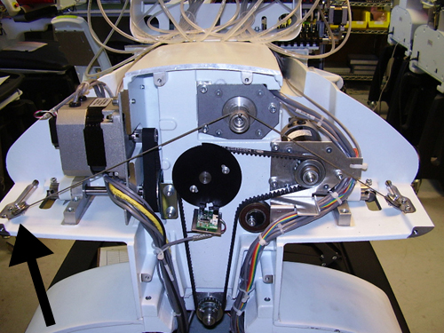
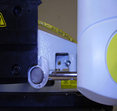
Figure 3 - Right Rear Pulley
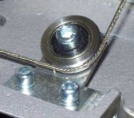
Figure 4 - Right Rear Pulley Close Up
7. Run the cable around the pulley shown in Figure 3 and Figure 4.
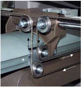
Figure 5 - Right Beam Cable Pulleys
(Arrows indicate direction of cable to the front)
8. Run the cable through the through hole in the back of the upper arm casting to the right rear carriage cable pulley down to the top right beam cable pulley.
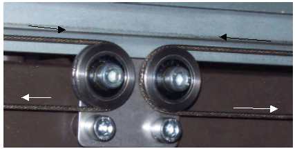
Figure 6 - Center Beam Cable Pulleys
(Arrows indicate direction of cable to the front)
9. Run the cable from the top right beam cable pulley around the right center beam cable pulley to the bottom right beam cable pulley.
10. Run the cable around the bottom right beam pulley (see figure 5), around the right front carriage pulley into the cable access hole to the front of the machine.
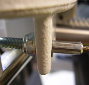
Figures 7 and 8 - X-Cable Clamp
11. Attach the washer and nut to the threaded end of the stud. Use needle nose pliers to hold the cable stud before tightening the nut to prevent the cable from twisting.
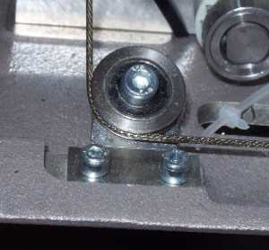
Figure 9 - Left Rear Cable Pulley
12. Run the left cable from the spool around the left rear cable pulley.
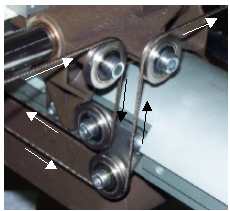
Figure 10 - Left Beam Cable Pulleys
13. Repeat steps 8-10 for the left side cable.
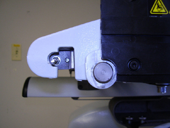
Figure 1 - Cable Tensioning Bracket
(Left side of machine)
14. 14. Install the washer and nut to the threaded end of the stud. Use needle nose pliers to hold the cable stud before tightening the nut to prevent the cable from twisting.
15. Tension the x-cable using the procedures prescribed in "X-Cable Tensioning".
16. Install the upper arm back cover.
17. Install the left and right transparent arm covers.
![]()