![]()
The take-up lever cam may wear out over time and need replacement. Replace the cam following these procedures.
|
|
This repair requires timing and other adjustments and should be done by a Melco authorized service technician. |
Replacement Part Needed: Take-Up Lever Cam
2. Remove both the left and right front arm covers.
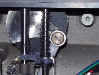
Figure 1 - Take-Up Lever Connecting Arm
3. Remove the screw connecting the connecting rod assembly to the take-up lever cam and disconnect the connecting rod from the take-up lever cam. Use a screwdriver that fits the slot correctly as the screw threads have red loctite (MS 222) applied and may be difficult to break loose.
|
|
CAUTION!! DO NOT DISASSEMBLE THE Z-SHAFT ITSELF OR ATTEMPT TO REMOVE IT! If you remove the retaining rings at either end of the z-shaft, the machine will have to be sent in to the factory for repair. The illustrations below are shown on a z-shaft that is removed from the machine for clarity purposes only. |
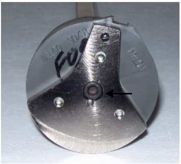
Figure 2 - Remove Center Screw
4. Remove the center screw connecting the z-shaft end plate to the upper z-shaft.
5. Remove the take-up lever cam (with the z-shaft end plate attached) from the upper z-shaft.
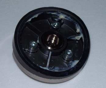
Figure 3 - Screws On Back of Take-Up Lever Cam
6. Remove the screws mounting the z-shaft end plate to the take-up lever cam.
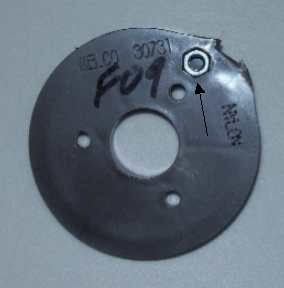
Figure 4 - Remove Hex Nut
7. Remove the M4 hex nut from the take-up lever cam and put it in the replacement cam.
8. Apply red loctite (MS 222) to the M4 screws and attach the z-shaft end plate to the take-up lever cam. Make sure the M4 hex nut does not fall out of the recessed hexagonal hole in the take up lever cam. Tighten the M4 screws to 10.5 in-lbs[1.2 Nm] of torque.
Figure 5 - Endplate w/Spring Pin Pressed in EndPlate- back view
9. Push the spring pin into the z-shaft end plate from the front until it is flush to the back of the end plate (see figure 5).
|
|
Important: When inserting the spring pin, make sure the spring pin teeth are facing down. |

Figure 6 - Alignment Groove in Z-Shaft
10. Align the spring pin in the z shaft end plate with the groove of the upper z-shaft and press onto the end of the shaft.
11. Push the spring pin back into the end plate if it slips out while pressing it onto the z-shaft.
12. Apply red loctite (MS 222) to the M5 screw and install it to the end of the upper z-shaft and tighten it to 66.5 in-lbs[7.5 Nm] of torque.
13. Apply red loctite (MS 222) to the upper connecting rod bolt and assemble the connecting rod assembly to the take-up lever cam. Tighten the bolt to 35 in-lbs[4 Nm] of torque. (Figure 1)
14. Install the left and right front arm covers.
![]()