![]()
|
|
This repair requires timing and other adjustments and should be performed by a Melco authorized service technician. |
Repair Parts Required:
Z-Home Sensor PCB Assembly (includes the bracket)
|
|
WARNING!! Do not take the covers off the machine without either turning the machine off or engaging the emergency button. The motors might move when the sensor is removed or the harnesses are disconnected. |
1. Either turn the machine off or engage the emergency stop button by pressing ![]() in.
in.
2. Remove the left and right transparent arm covers and set the hardware aside for reuse.
3. Remove the upper arm back cover and set the hardware aside for reuse.
4. Disconnect the z-home harness lead from the PCB connector socket.
5. Remove the two M4x10mm cap head socket screws, M4 split lock washers, and M4 flat washers that mount the bracket to the upper arm and remove the Z-home sensor PCB assembly from the machine.
6. Install the replacement Z-Home Sensor PCB Assembly using the hardware you removed from the old assembly using the Z Home Sensor Fixture (PN: 32980) to correctly realign the aseembly. See Figure 1.
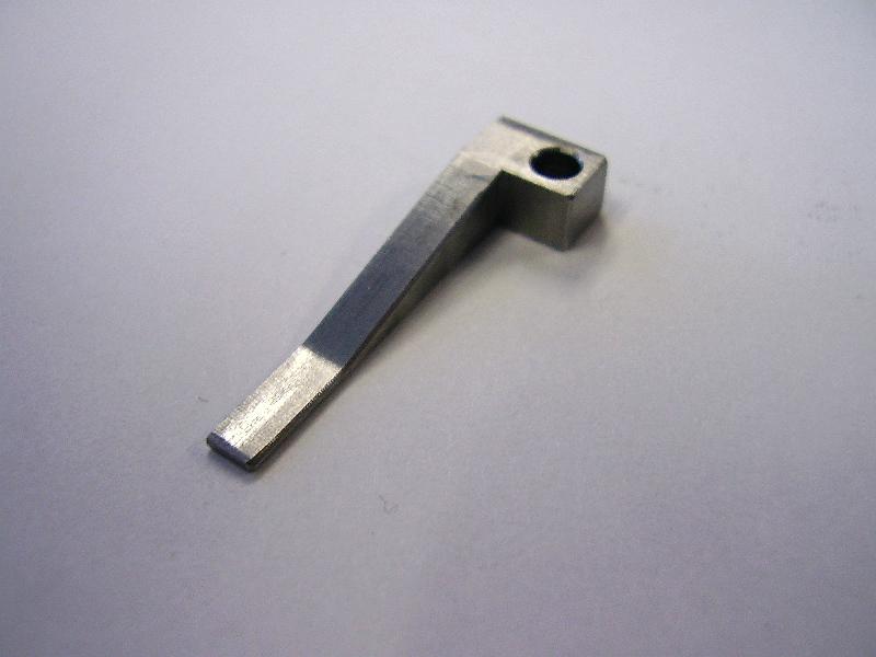
Figure 1 - Z-Home Sensor Fixture
7. Align the mounting bracket of the replacement PCB using the Z Home Sensor Fixture (PN: 32980). Make sure the fixture contacts the outside face of the opto sensor on the PCB. Position the bracket until the fixture contacts the outside diameter of the Z Home Flag. See Figure 2.
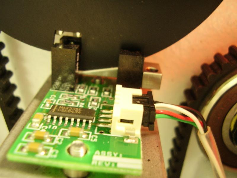
Figure 2 - Z-Home PCB Mounting Bracket
NOTE: Make sure that the flag is centered front to rear between the sensors on the optical PCB. Adjust PCB if required.
8. Tighten the screws to Melco Torque Specifications and remove the fixture.
9. Connect the z-home harness lead into the PCB connector socket.
10. Use a small plastic cable tie and tie the connector snug by attaching the cable tie around the PCB such that the cable tie holds the connector in place. Failure to do this might result in the connectors coming loose which can create difficulties in troubleshooting. See Figure 3.

Figure 2 - Cable Tie Around PCB
11. Reinstall the upper arm back cover and tighten the screws to Melco Torque Specifications.
12. Reinstall the left and right transparent arm covers and tighten the screws to Melco Torque Specifications (use minimum torque required for clamping plastic materials).
![]()