![]()
Take up levers require replacement whenever they are damaged in anyway. No fixtures are required to perform this procedure, but it must be completed by following these instructions explicitly.
Replacement Parts Needed:
one take up lever assembly (for each take up lever requiring replacement)
1. Remove the needlecase access cover.
2. Remove the needlecase cover.
3. On the left end of the take up lever axis (take up lever shaft), use a black marker and mark on the axis where the inside edge of the left take up lever mounting block clamps onto the axis.
4. Turn the main power switch ON.
6. Shut the machine OFF.
7. Remove the two screws mounting the right color change shaft mounting block and loosen the screw clamping the color change shaft. Remove the mounting block.
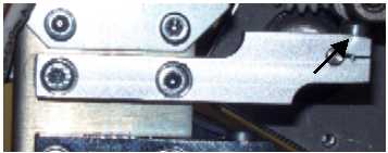
Figure 1 - Right Take Up Lever Bar Mounting Block
8. Loosen the top screw in the right take up lever mounting block.
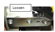
Figure 2 - Right Take Up Lever Bar Mounting Block
9. Loosen the two top screws holding the take up lever bar in the left take up lever mounting block.
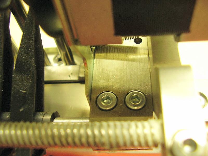
Figure 3 - Screws on Take Up Lever bar
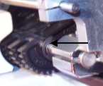
Figure 4 - Retaining Clip
10. Remove the retaining ring from the groove on the left side of the left take up lever axis. Set it aside for reuse.
11. Tap on the right side of the take up lever axis until the spacer on the right side can be removed and set it aside for reuse.
12. While holding the take up lever axis up slightly, slide each take up lever off towards the right side of the machine and remove them one at a time until you get to the first take up lever that needs to be replaced (closest to right side).
13. Install a new take up lever assembly in place so that the back groove (larger than the valleys) sits on the guide on the take up lever guide.
14. Tap the take up lever bar through each consecutive take up lever, replacing the remaining defective ones using the procedure in step 9.
15. Before you tap the bar though the end of the last take up lever, install the spacer into place and tap the take up lever though the spacer.
16. Install the retaining ring in the groove on the left end of the take up lever axis.
17. Tap the take up lever axis into the bore on the right take up lever bar mounting block so that the space between the last take up lever body and the right block is .020"±.003" (with all of the take up lever bodies pushed against the retaining ring).
18. Tighten the top screws in both take up lever bar mounting blocks to Melco Torque Specifications.
19. Remount the right color change mounting bracket, leaving the screws loose.
20. Tighten the top screw in the right color change mounting bracket to Melco Torque Specifications.
21. Turn the machine ON. The machine will move each component to "home".
23. Tighten the right color change mounting bracket screws to Melco Torque Specifications.
24. If you do not have further work in the needlecase assembly, install the needlecase cover and access cover.
![]()