![]()
This procedure can be performed by the machine operator as long as the following procedures are followed explicitly.
This procedure requires the use of a 0-10 lb. Melco Force Gauge and a Universal Force Gauge Adapter, a 3mm hex wrench.
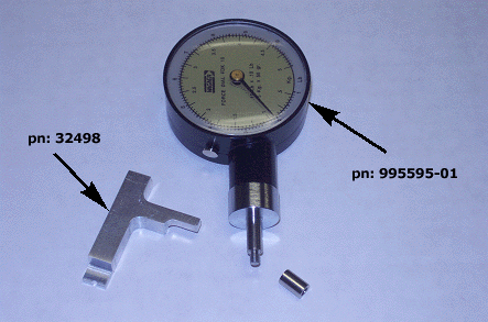
Attach the Universal Force Gauge Adapter, PN 32498, to the 0-10 lb. Force Gauge, PN 995591-01 (screw adapter on the end of the gauge).
Turn the machine OFF.
Remove either one of the upper arm transparent covers and the innermost back screw of the other one (remove screws with a 3mm hex wrench).
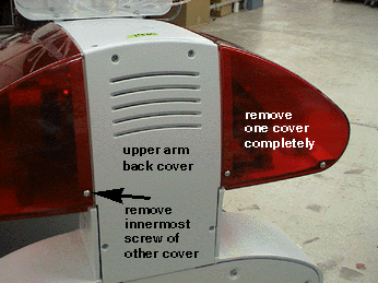
Remove the upper arm back cover (remove screws with a 3mm hex wrench).
Locate the z-drive belt and the z-motor mounting bracket.
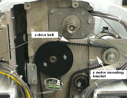
Using a ruler (preferably metric) mark the z-motor mounting bracket 17mm (0.67") below the top edge of the bracket.
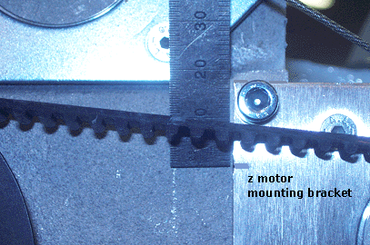
Position the gauge adapter (with gauge attached) as shown in the image below.
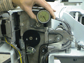
The right side of the adapter should be lined up with outside edge of the motor mounting bracket.
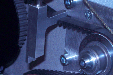
Push down on the force gauge until the top of the belt lines up with the mark on the mounting bracket. The force should be 6.8 ± 0.3 lbs.
To adjust the tension of the z-drive belt, hold the idler pulley steady with one hand and loosen the screw with a 3mm hex wrench. Turn the z-idler pulley clockwise to increase the tension (counterclockwise to reduce tension) and then tighten the screw to Melco Torque Specifications.
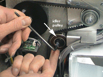
Measure the tension again (as specified in Steps 7 and 8) and if it is not correct, repeat step 9 until the tension is set to the specification.
Reinstall the covers in the reverse order that you removed them. Tighten the screws to Melco Torque Specifications.
Do a short machine functional test to verify proper z-axis timing (needle bars synchronized, with rotary hook movement).
|
|
Note: If a BRECO meter is used to measure the tension, the measurement should be 72-78 Hz. |