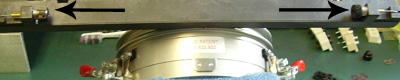
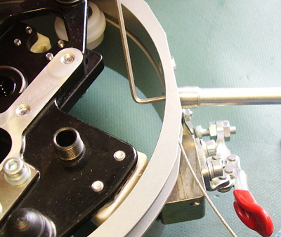
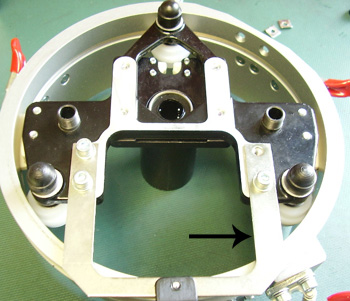
The driver bar cable, when tensioned properly, moves the driver precise amounts during embroidery. If the cable tension falls out of adjustment, embroidery quality will suffer.
|
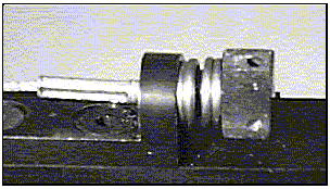
Figure 1 - Properly Adjusted Coil
|
|
|
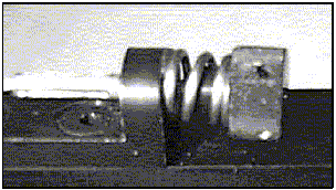
Figure 2 - Under Compressed Coil |
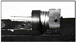
Figure 3 - Over Compressed Coil
|
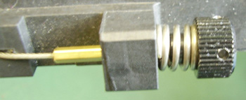
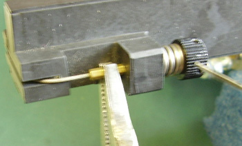
To check the cable tension, look at the spring coils holding the cable. The coils should be closed as shown in Figure 1.
If the coils are open as shown in Figure 2, tighten the cable by pulling on the cable slightly with your fingers as you tighten the thumb screw.
|
|
CAUTION!! DO NOT over-compress the coils or you may cause excessive wear to the cable terminal. Figure 3 shows an over-compressed coil. |
Driver Bar Cable Replacement:
This procedure requires the following tools:
For screws/washers, securing the cable in back
Bent Allen 2mm
Nut Driver 7/32
222 red Loctite
To remove bar holder
3mm bent or 75mm blade
To install cable
Quick Grip micro bar clamp
Needle nose vise grip
1.5mm bent or 21mm blade
Mallet
|
1. Loosen and remove both screws on the driver bar. |
|
|
2. Remove the 2 back nuts, washers, and screws.
|
|
|
NOTE: You can remove the bar holder for easier access to the cable, but it is not necessary. |
|
|
3. Take the old or broken cable off. |
|
|
4. Get the new cable. |
|
|
5. Insert the 2 screws removed in Step 2. |
|
|
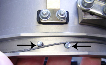
6. Route new cable around screws (see picture). It does not matter which end of the cable goes up and which goes down. |
|
|
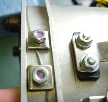
7. Put the washers on, making sure the flat side is against the cable. |
|
|
8. Add Loctite to the ends of the screws. |
|
|
9. Put the nuts on the screws, leaving the nuts loose. |
|
|
10. Crisscross the cable (see picture). |
|
|
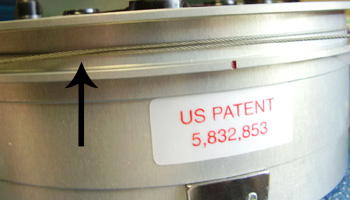
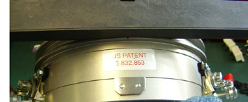
11. Center the crisscrossed cables under the red line above the US Patent sticker.. |
|
|
12. Put the driver bar on with the centered cables in the groove. |
|
|
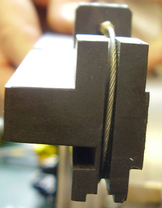
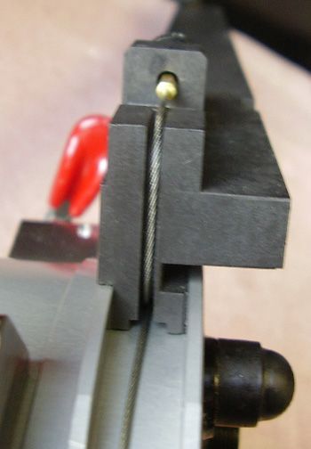
13. Loop the cable around and insert the threaded portion in the holes of the driver bar. Make sure the cable is in the groove on the side of the bar. |
|
|
14. Thread the spring and screw on the end of the cable. |
|
|
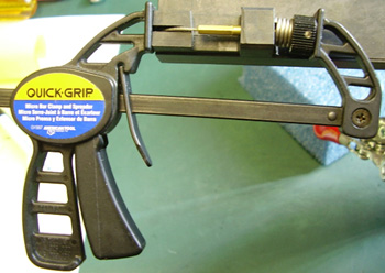
15. Use the Quick Grip tool to compress the spring and leave on. |
|
|
16. Repeat Step 13 and 14 for the other side of the cable. |
|
|
17. Line up the center of the driver bar with the center of the driver (following the red line above the US Patent sticker). |
|
|
18. Remove the Quick Grip from the first side of the driver bar. Screw the spring on while holding the cable in place. |
|
|
19. Move the Quick Grip to the other side of the driver bar and use it to get the spring compressed and the screw tightened on. |
|
|
20. Tighten the first side more if necessary. |
|
|
21. Use the mallet to knock the bar into place if the center of the driver bar and driver is off. Tighten springs again if needed. |
|
|
22. Tighten the nuts from Step 9 down on the back of the driver against the cable. |
|
|
23. Make sure the cable is in the open groove on the driver bar. Move it around if necessary. |
|
Click on the below links to go to the next procedure you wish to perform: