![]()
WARNING! Do not attempt to lubricate the machine while it is in operation.
Tools and supplies needed for these procedures
are provided in your operator's kit.
Using the correct lubricants properly and when specified by scheduled maintenance
is critical to the operation of the AMAYA. Failure to use the proper
lubricants as specified can shorten the usable life of internal components
and can void the warranty. Using the wrong lubricants can adversely
affect your machine. The recommended and authorized lubricants to
be used on the AMAYA are specified below:
Melco Part Number: |
Part Name |
Comments |
761003-01 |
Oiler, 3/4 oz. bottle |
sewing machine oil (order from Melco Mart) |
32078 |
Grease, EMB-Polymer, 8 oz bottle |
polymer light grease |
32079 |
Grease, Multi-purpose (Lithium), 8 oz bottle |
heavy grease |
The following table summarizes the lubrication points and schedule for your machine. The table also lists which type of lubrication you should use for each lubrication point.
Please note that these schedules are meant to be used as guidelines. Depending on many circumstances (such as environment, garment types sewn on, etc.), you may need to lubricate your machines more or less frequently. Follow a lubrication schedule that best fits your needs to take care of your machine(s).
|
WARNING! Do not attempt to lubricate the machine while it is in operation. |
|
Important: The color change lead screw is lubricated for life and should NEVER be lubricated by the user or a technician. |
Item |
Lubricant |
Item |
Lubricant |
Item |
Lubricant |
Needle Drive: |
|
Clean Only |
|
Clean Only |
Item |
Lubricant |
|
|
|
Thread Feeder Rollers (Inspection, Cleaning, and Lubrication) |
Item |
Lubricant |
Item |
Lubricant |
|
|
Every 50,000,000 Stitches
Item |
Lubricant |
Item |
Lubricant |
Once a Year
The following belts should be checked once a year: X-Cable, Y-Axis Timing Belt, and Z-Drive Belt. You can either have a Melco Service Technician check these belts for a charge (contact Melco Service-303.457.2025), or you can perform these checks yourself. To perform these checks, you will need to purchase the following tools / fixtures from the Melco Parts Department (800.877.4272), and follow the procedures in the AMAYA Technical Manual.
|
See the AMAYA Technical Manual, see X-cable Tensioning , Y-axis timing belt Tensioning , Z-drive Belt Tensioning |
|
CAUTION! Some of the lubrication
procedures instruct you to remove the right/left front covers.
Do not turn the AMAYA machine off, then on again when either
of these covers is removed. This will cause the machine
to color change, which will cause the needle bars to fall out.
Do not move the needlecase at all when either of the front
covers is removed. If you proceed without this cover damage
to your machine will occur and a service call will be necessary.
|
As long as you have maintenance timers enabled
(see Timers
Tab), you will be guided through the lubrication of your machine with
maintenance timers (see example below).
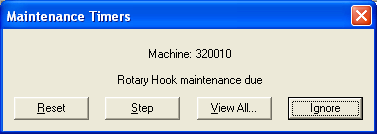
Each time a maintenance timer reaches zero, a dialog box pops up indicating that you need to perform that maintenance. To perform the maintenance, click the Step button. You will then be guided through performing the maintenance step by step. (These step-by-step procedures are condensed versions of the lubrication procedures in this section; these step-by-step procedures also perform the machine commands, such as head up, for you.) If you successfully complete the maintenance, the timer will reset when you are finished. If you receive an error while you are performing the maintenance that prevents you from successfully completing the procedures, the timer will not reset. You will need to restart the step by step procedure and complete it successfully.
If you click the Reset button, the stitch count for that timer will be reset to zero. However, it is strongly recommended that you do not reset timers without performing the required maintenance. Neglecting the maintenance of your machine could damage your machine. You can click the View All button to display all of the maintenance timers (displayed on the Timers Tab). If you click the Ignore button, the dialog box will be displayed again after each successive design is completed.
You can perform the step through procedures at any time for any timer interval. To do this, open the Settings menu and click the Timers tab. Click the Step button for the timer interval to step through the lubrication for that interval. If you successfully complete the maintenance, the timer will reset when you are finished. You can click on any of the pictures in the step through procedures and they will enlarge.
You can perform the step-through procedures provided by the timers without using the procedures below (unless you want to refer to the pictures). If for some reason you are lubricating without using the step-through procedures, follow the procedures below.
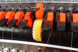
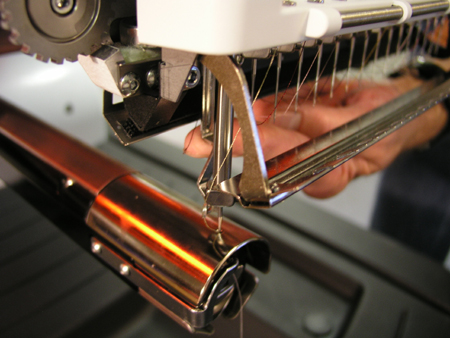
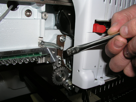
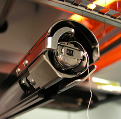
Follow these steps for rotary hook lubrication:
Remove the bobbin case from the hook assembly.
Clean the rotary hook area with a brush (or canned or compressed air). While the bobbin case is out of the machine, you may want to clean it as well (click here for instructions).
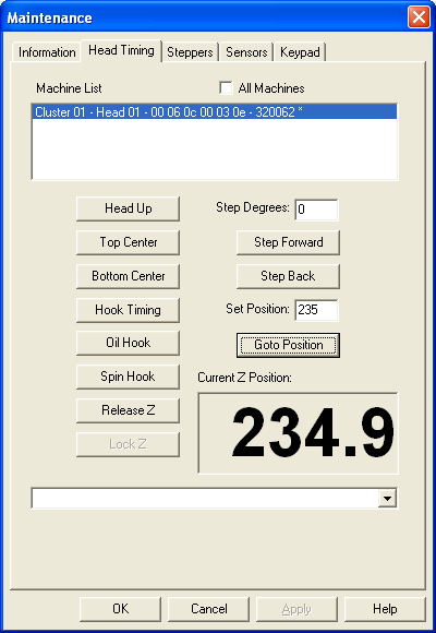
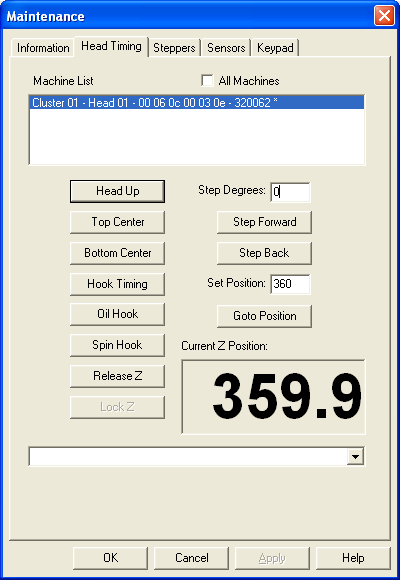
Select the Maintenance menu in AMAYA OS.
Click on the Head
Timing tab.
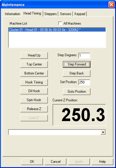
If performing maintenance on all machines in a flex cluster, check the All Machines box. If performing maintenance on a single machine in the cluster, uncheck the All Machines box, and click the machine in the Machine List.
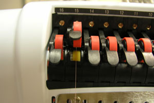
Click the Oil Hook button.
Place one drop of sewing machine
oil in the rotary hook as shown in the image below. Be careful not
to over oil.
If you do squeeze too much oil, then you may need to run a sewout on
some scrap fabric. This will prevent the excess oil from getting
all over your garment.
Click the Spin Hook button in the Head Timing tab and the hook rotates for several seconds to spread the oil.
Replace the bobbin case in the machine, and thread the needle if required.
Color change to Needle 16
(press and hold ![]() , then
press
, then
press ![]() until you
reach needle 16.)
until you
reach needle 16.)
Select the Maintenance menu in AMAYA OS.
Select the Head
Timing tab.
If performing maintenance on all machines in a cluster, check the All Machines box. If performing maintenance on a single machine in a cluster, uncheck the All Machines box, and click the machine in the Machine List. These options will be grayed out if performing maintenance on Flex machines.
Click the Top Center button to take the head to the upper top position.
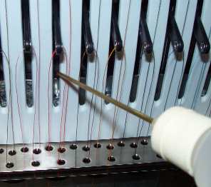
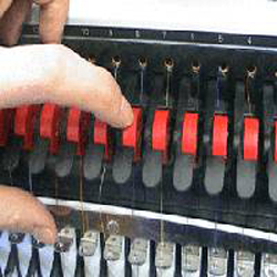
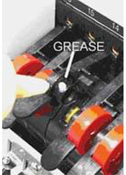
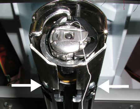
Put 25 drops of sewing machine
oil in the oiling channel located on the left take-up lever rail next
to the left side of the needle case assembly. (See image below).
Allow the machine to sit without running for 2-3 minutes. This
will allow the oil to seep through the felt onto the assemblies intended
to be lubricated in this process (Reciprocator Guide, Cam Follower
Shaft, Connecting Rod Pin).
Click the Head
Up button.
Color change
to Needle #1 or Needle #16 (press and hold ![]() , then
press
, then
press ![]() or
or ![]() ).
).
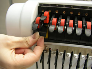
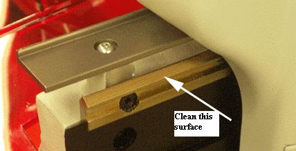
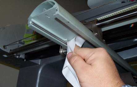
Using a clean, dry cloth, wipe the surface of the upper v-rail clean as shown in the photograph (IMPORTANT: Make sure there is no oil or grease is applied to the upper v-rail).
Color
change all the way all the way to the other side (press and hold ![]() , then press
, then press ![]() or
or ![]() ).
).
Repeat step 2 for the other side.
Perform maintenance on the wide angle cap frame driver after 2,000,000 stitches have been sewn using the cap frame driver.
Move the x-carriage all the
way to the back of the machine (press and hold ![]() ,
then press
,
then press ![]() ). (If the driver
is installed on the machine).
). (If the driver
is installed on the machine).
Wipe any lint off the driver
shafts and use compressed air to blow any dust off the entire assembly.
|
|
|
|
|
|
|
|
If there is a hoop installed on the machine, remove it.
Press
the Emergency Stop button ![]() to prevent accidental starting of the machine.
to prevent accidental starting of the machine.
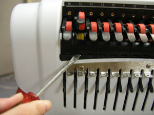
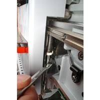
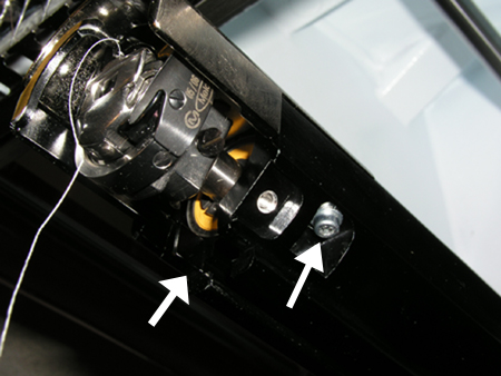
Remove the Rotary Hook Guards by loosening the screws as shown below.
NOTE: These screws do NOT need to be removed in order to remove the guards.
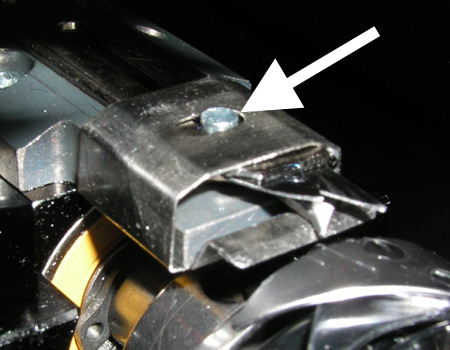
Remove the Needle Plate by removing the two screws from the bottom of the extrusion.
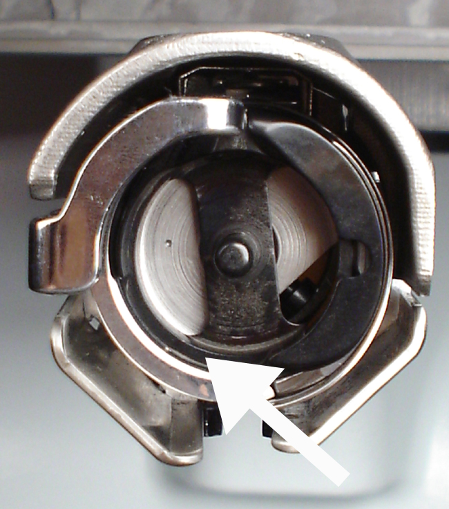
Clean the exposed areas with compressed or canned air.
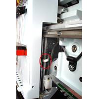
Apply one drop of oil on the pin as indicated in the image below.
Reinstall the Needle Plate and the Rotary Hook Guards.
Disengage the emergency stop button by twisting it.
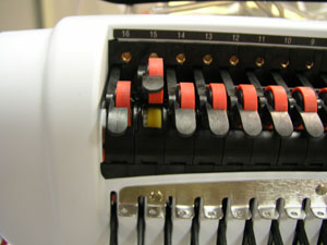
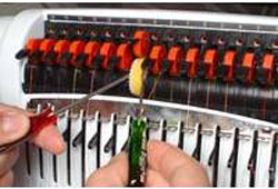
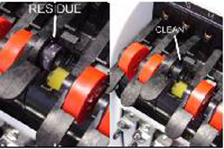
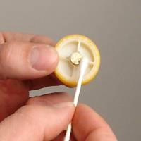
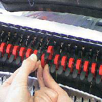
For this maintenance procedure, you will need to inspect each thread feed roller. Repeat the following procedure for each roller:
(This section provides part numbers for the parts you may need to replace.
Please note that it is possible for part numbers to change after
the release of this help system).
See the Thread
Feeder Roller Troubleshooting section for more in-depth information
about thread feeder rollers.
|
|
|
|
|
|
|
|
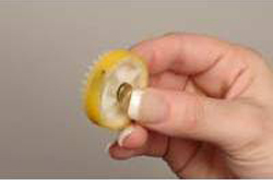
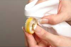
NOTE: A small amount of alcohol may be used to remove any oil or grease. |
|
|
|
|
|
|
|
|
|
|
|
|
|
|
|
|
|
|
|
|
|
|
|
|
|
|
|
|
|
|
|
|
|
Move the x-beam all the way forward (press and hold
![]() , then press
, then press ![]() ), and all the way to one side (press and hold
), and all the way to one side (press and hold
![]() , then press
, then press ![]() or
or ![]() ).
).
Using a clean cotton rag, wipe
off any dust/lint accumulation from both of the carriage rails (see
the image below for the location of these rails).
Again using a cotton rag, apply
a very thin layer of multi-purpose lithium grease to both carriage
rails (one in the front and one in the back of the beam) from underneath
the beam. If you can see clumps of the white grease after you
have applied it, then you have put too much. Wipe off excess
grease before proceeding.
Move the beam all the way to
the other side (press and hold ![]() ,
then press
,
then press ![]() or
or ![]() )
and repeat step 2 on the other end of the carriage rails.
)
and repeat step 2 on the other end of the carriage rails.
|
CAUTION: DO NOT APPLY GREASE TO THE Y-RAILS. If you do so, machine performance will be impaired. Grease will attract dust, which will serve as an abrasive against the bearings and the shaft. |
If you follow the procedure as described below, it is not necessary to remove the machine’s red transparent covers. If desired, the red covers can be removed to make the oiling holes easier to access.
Move
the x-carriage to the center of the y-rails.
Use
the image below to locate the oiling hole on the top center of each
bearing block assembly.

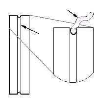
As
shown in the image below, place the oiler under the red transparent
cover so that the tip touches the oiling hole on the bearing block
assembly. (You may find it helpful to bend the oiler tip). Add five
drops of sewing machine oil to the oiling hole. Repeat for the oiling
hole on the other side of the machine.
|
|
|
|
|
|
|
|
|
|
|---|---|
|
|
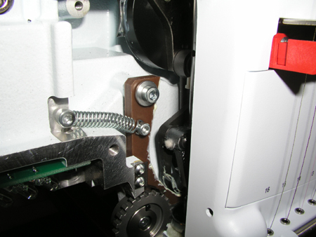
NOTE: The presser foot cam follower is the black plate located directly below the white, plastic pad on the presser foot shaft. |
|
|
|
|
|
|
|
|
|
|
|
|---|---|
|
|
NOTE: The cam shown in this photograph is white. Newer machines may have a brown presser foot cam. |
|
|
|