User Interface Harness
![]()
The User Interface harness connects the user interface (keyboard) to the Main PCB at connector location J23.
|
|
CAUTION!! Do not confuse the user interface harness with the similar looking Ethernet harness. The user interface harness connects to J23 on the Main PCB while the Ethernet harness connects to J1. Both connectors are the same type, so make sure you are connecting to the correct connector. |
Failure of the User Interface harness will generally be caused from handling of the harness during other repairs or maintenance. It should rarely fail on its own without being handled.
Replacement Parts Needed:
harness, User Interface
twist-lock cable ties (available at most hardware stores in the electrical section)
Replacement Procedures:
1. Turn the machine off.
|
|
CAUTION!! Use extreme care not to drop metallic objects, tools, or other conductive material on the Main PCB when you have the base cover removed. If you drop such objects on the Main PCB, it can severely damage the electronics which will be very expensive to repair. |
2. Remove the right plastic side cover, base cover, lower arm rear cover and the upper arm rear cover.
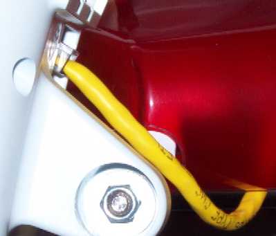
Figure 1 - User Interface Harness Connection
3. Disconnect the user interface harness from the user interface assembly, shown in Figure 1.
4. From behind the upper arm, pull the user interface harness through the right upper arm access hole.
5. Pull the user interface harness out the right wiring channel and remove any twist-lock cable ties that bundle the user interface harness to adjacent harnesses, down to the back of the machine.
|
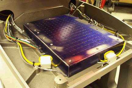
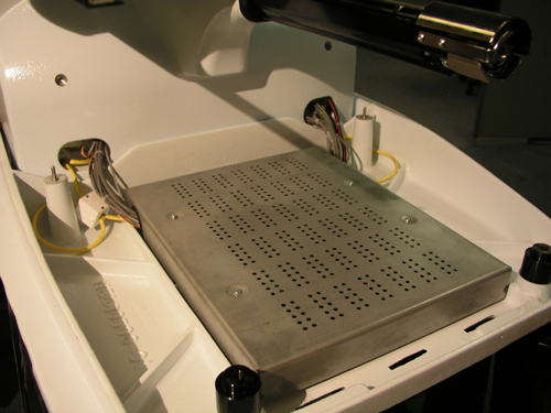
Figure 2a - 32188 Series EMI Cover |
Figure 2b - 32232 Series EMI Cover |
6. Remove the EMI cover from the main control board by removing the screws from the edge of the cover. Remove the radio interference ferrite from the harness.
7. Remove any twist-lock cable ties that tie the User Interface harness to adjacent ones and disconnect it from the main PCB at connector location J23.
8. Remove the old User Interface harness.
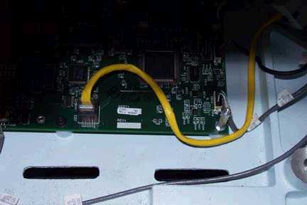
Figure 3 - User Interface Harness in PCB
9. Connect the replacement harness to the main PCB at connector location J23.
|
|
Note: Make sure that you fold the harness as indicated in Figure 3. |
10. Replace the EMI cover carefully following the procedures provided in "EMI Cover - New Type" or "EMI Cover - Old Type" (see Figures 2a and 2b for pictures) and the radio interference ferrite.
11. Run the User Interface harness through the right wiring channel following the same path as the adjacent harnesses.
12. Connect the other end of the User Interface harness to the back of the User Interface assembly as shown in Figure 1.
13. Replace the twist-lock cable ties on the harness tieing it to adjacent ones.
14. Replace the EMI cover carefully following the instructions provided in "EMI Cover - 32232 Series" or "EMI Cover - 32188 Series" as appropriate (see Figures 2a and 2b for pictures of the covers).
15. Replace the base cover.
16. Reinstall the rear covers and tighten the screws to Melco Torque Specifications.
17. Replace the right upper arm transparent cover.
18. Turn the machine on and load the AMAYA OS ( AMAYA OS).
19. If the software shows the machine being connected, the User interface harness and the circuitry on the main PCB is working correctly.