![]()
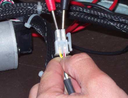
Figure 1 - Resistance Measurement of Servo Motors
|
Servo Mtr |
Resistance Specification |
|
X |
3.65±10%Ω |
|
Y |
2.28±10%Ω |
|
Z |
1.04±10%Ω |
When measuring the resistance with a ohmmeter or multimeter, it is strongly recommended that it be done with a calibrated meter rated with resistance reading accuracy equal to or better than ±1%. Fluke™ multimeters generally meet this accuracy requirement. Make sure you get this specification when you purchase multimeters used to troubleshoot machine errors on the AMAYA.
If you use a meter that does not meet this accuracy specification, go on the assumption that if the readings between the phase leads of the motor are consistent (nonzero resistance) that the motor is probably good. The machine should be considered defective if the measurements are substantially lower than the ranges specified in Step 1 shown in the above table. If you have a phase that has close to a zero reading or measurements between phase leads that are not consistent, then the motor is defective.
"Ohming out a motor" or measuring the resistance between each of the phase wires is easily measures by connecting the leads from the meter to the nonground wires (disregard the green wires). The resistance between each of the phase combinations (3 combinations on all three servo motors) should be consistent and within the ranges shown in Step 1 in the table above.
![]()