![]()
Before working with the z-motor assembly, you need to determine if the motor is the short z-motor (Melco PN 30622) or the long z-motor (Melco PN 30622-01). To determine this, measure the length of the z-motor. The length of the long motor is 114.5mm [4.5"], and the length of the short motor is 94.7mm [3.73"].
Besides in case of an x-motor failure, the Z-motor assembly should also be replaced when the resistance between each of the phases is inconsistent or substantially different than 1.04±10%Ω for the short z-motor and 0.57±10%Ω for the long z-motor. In addition, the resistance between each of the phase wires should be relatively consistent with the other wires.
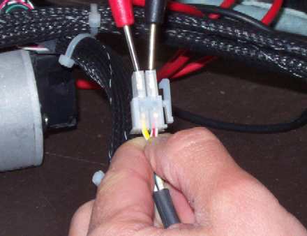
Figure 1 - Measuring Resistance Between Motor Phase Wires
Resistance of the z-motor phase wires can be measured at the connector with an Ohmmeter as shown in Figure 1 above. Disregard the green (ground) wire and measure the resistance between each combination of the other 3 wires.
Measuring resistance however, is not the only factor to be used in determining whether to replace a motor or not. Examples of other issues that should be considered is how freely and smoothly the spindle on the motor turns. These factors are covered in the troubleshooting section of this manual.
Replacement Parts Needed:
Z-Axis Brushless Servo Motor
6-11 inch Cable Ties (to re-tie the harnesses after installing the new motor) (available through the Melco Parts Department (PN: 340139-07) and also in the electrical section at most hardware stores )
1. Turn the machine OFF.
2. Remove the left transparent arm cover and the screw from the back of the right one.
3. Remove the upper arm back cover.
|
|
CAUTION!! Use extreme care not to drop metallic objects, tools, or other conductive material on the Main PCB when you have the base cover removed. If you drop such objects on the Main PCB, it can severely damaged the electronics which will be very expensive to repair. |
4. Remove the base cover.
5. Remove the lower arm rear cover.
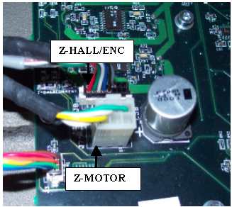
Figure 2 - Z-Motor PCB Connections
6. Disconnect both the z-motor harness and motor and hall sensor leads (marked "CONTROL PCB Z MOTOR" and "CONTROL PCB Z HALL/ENC") from the main PCB at connector locations J7 and J8.
7. Use a small pair of wire cutters and cut off the cable ties that tie the z-harness to the user interface harness.
8. Pull the z-harness all the way through the cable through-hole to the back of the machine and let the harness hang off the back of the machine.
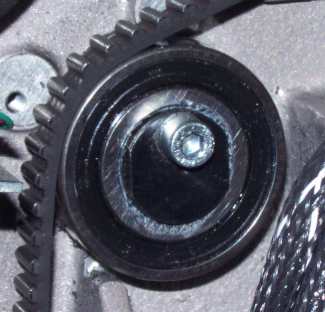
Figure 3 - Z-Belt Idler Pulley
9. Slowly loosen the z-belt idler pulley to remove the tension from the z-drive belt.
10. Cut all of the cable ties that tie the x- and z-harness leads together.
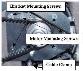
Figure 4 - Z-Motor Mounting Screws
11. Remove the cable clamp located at the bottom of the z-motor mounting bracket.
12. Remove the bracket mounting screws as shown in Figure 4 above.
13. Pull the x-cable out of the way and remove the z-motor from the machine.
14. Remove the z-motor timing pulley from the z-motor.
15. Remove the z-motor mounting bracket from the z-motor, install it on the replacement motor, and tighten the screws to Melco Torque Specifications.
|
|
CAUTION!! Do not drop the z-motor timing pulley or allow the star washers that are pressed inside the bore to come loose. If the star washers fall out or come loose, the timing pulley must be replaced. If you install a timing pulley with the star washers loose or missing, damage to the machine will likely result. |
16. Install the z-motor timing pulley onto the z-motor shaft and tighten the screw to 8 in-lbs[0.9 Nm]. This must be done with a reliable torque wrench.
17. Mount the motor assembly to the upper arm as shown in Figure 4 above and tighten the screws to Melco Torque Specifications.
18. Use a cable tie and tie the z-motor harness to the adjacent harness leads at the z-motor mount standoff (x-harness leads and the Control Board LED lead).
19. Attach the cable clamp to the z-motor lead (marked "CONTROL PCB Z MOTOR") and attach the cable clamp at the bottom of the z-motor mounting bracket as shown in Figure 4. Tighten the screw to Melco Torque Specifications.
20. Use a cable tie and tie the z-motor harness leads and the adjacent leads together right before the clamp.
21. Tie the z-motor harness to the adjacent harnesses at about every 3 inches and route the z-motor harness leads down the back of the machine to the cable access hole. Connect the motor harness and hall/encoder leads to the main PCB.
22. Tension the z-drive belt as specified in Z-Belt Replacement and Tensioning.
23. Unless you have additional work to do on the inside of the machine, install the covers back onto the machine in the reverse order you removed them.
![]()