![]()
Typically, the optical sensor PCB needs to be replaced when it gets too dirty. The sensors can not be cleaned with any solvents as they will nearly always be damaged doing so. The only process that can clean the sensors is compressed air. If that does not clean the sensors enough to use, the optical sensor PCB has to be replaced.
Replacement Parts Needed:
Optical Sensor PCB
Two M3x0.5x6mm button head socket screws (recommend replacing screws after removing them)
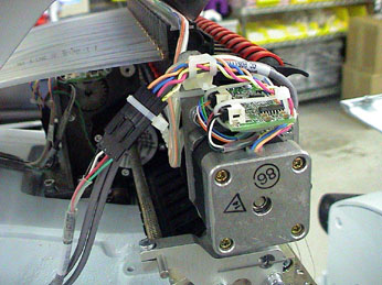
Figure 1 - Optical Sensor PCB, Top of Needlecase Assembly
1. Turn the machine off.
2. Remove the needle case access cover.
3. Remove the two button head screws connecting the needlecase cover to the needlecase assembly.
4. Remove the needlecase cover.
5. Cut the cable ties (if installed) on the PCB and remove them.
6. Disconnect the two harnesses from the PCB connector sockets one at a time, using caution to avoid damaging the wires or connectors.
7. Remove the two M3x6mm button head socket screws from the top of the PCB and remove the PCB. Throw the old screws away.
8. Install the new PCB in the position that the old PCB was removed from. Position the PCB so that the flag is as perfectly centered between the sensors as possible. Make sure the flag does not hit either of the sensors.
9. Install two new M3x6mm button head screws and tighten them to Melco Torque Specifications.
10. Connect the harnesses into the connector sockets (they will fit only their respective connector sockets) on the PCB.
11. Use small plastic cable ties and tie the connectors snug by attaching the cable tie around the PCB such that the cable tie holds the connector in place. Failure to do this might result in the connectors coming loose which can create difficulties in troubleshooting. (See Figure 1.)
12. If you are not doing any other work on the needlecase assembly, install the needlecase cover and the access cover back into place.
![]()