![]()
|
|
This repair requires timing and other adjustments and should be done by a Melco authorized service technician. |
The color change optical sensor requires replacement whenever the optical sensors which are permanently wired to the harness are dirty and can not be cleaned, damaged due to mechanical failure or misalignment, or when they just simply fail.
There are two optical switch assemblies associated with the color change function:
One is installed in the needle case assembly that senses the color change home. This sensor tells the Main PCB where the needle case is how far the needlecase must move and in what direction to go to "color change home."
The other sensor is installed in the lower front of the upper arm assembly and senses the needlecase index position (the active needle bar is centered on the sensor). This sensor is key to needle centering to the needle plate hole.
|
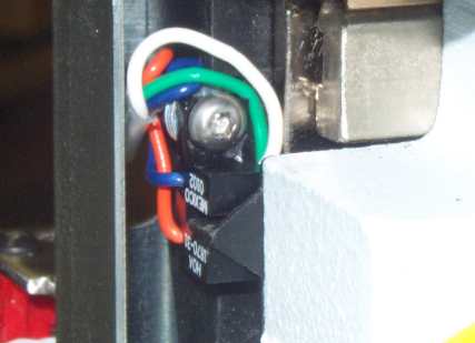
Color Change "Home" Optical Sensor |
Color Change "Home" Sensor (Needlecase four-pack removed from machine for illustration only) |
Generally, only one of these will require replacement.
Replacement Parts Needed:
optical switch, 0.07" slot, 18.0"
3" cable ties (available from most hardware stores in the electrical section)
Replacement Procedures:
Color Change Home Sensor: (located on right back side of needlecase assembly)
1. Color change to needle 16.
2. Remove the needlecase access cover and the needlecase cover.
3. Cut the cable tie that bundles the cables at the top left of the needlecase assembly. Unlatch the cable holder that holds the cables.
4. Disconnect the optical switch interface cable from the optical sensor PCB mounted on the top left of the needlecase assembly (right above the grabber stepper motor).
5. Remove the screw and washers that mount the optical sensor to the back right of the needlecase assembly and remove the entire assembly from the needlecase.

Figure 2 - Cable Routing on Right Side of Needlecase
6. Run the new optical sensor cable through the access hole in the needlecase connector first from the backside to the front and route the cable as shown in Figure 2.
7. Install the replacement sensor to the needlecase and center it over the flag (part of the right upper arm front cover) (see Figure 1), making sure the sensor does not rub against the flag. Tighten the screw to Melco Torque Specifications.
8. Run the sensor cable up and around the needlecase assembly and secure wires into the holder.
9. Connect the sensor cable to the optical sensor PCB on the top right of the needlecase assembly. Tie the harness connector to the PCB with a cable tie to prevent them from coming loose during machine operation. Position the cable tie between the harness wires on the center of the connector.
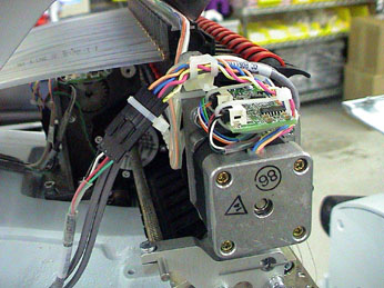
Figure 3 - Tie Cables at Grabber Stepper Motor Mounting Bracket
10. Add cable tie to the wire bundle as shown in Figure 3.
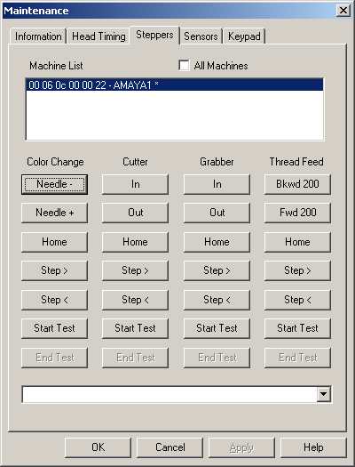
Figure 4 - AMAYA OS Steppers Menu
11. Start the AMAYA OS and click on the "Maintenance" menu from the AMAYA OS main menu and select the "Steppers" tab.
12. Click on the "Step<" button under the "Color Change" column and observe the sensor to make sure it does not hit the color change index flag. If it appears like the sensors are going to hit the flag, STOP, and color change back to needle 16 and readjust the sensor. Then repeat this procedure.
13. Reinstall the needlecase access cover and the needlecase cover.
Color Change Index Sensor:

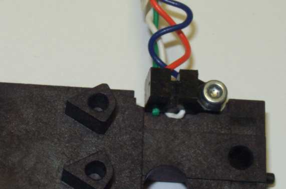
Figure 5 - Color Change Index Sensor Installed
(Needlecase removed for illustration only)
1. The needlecase can be removed for the purposes of replacing the color change index sensor, however, it is strongly discouraged. Once you do that additional alignment procedures will need to be accomplished. Instead, follow these procedures to replace this sensor.
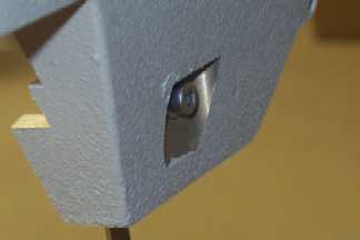
Figure 6 - Optical Switch Mounting Screw
3. Remove the right upper arm front cover.
![]() CAUTION!! Do not move the needlecase or turn the machine off and on while this cover is removed. If you proceed without this cover damage to the machine will occur. Disclaimer: Melco will not be held responsible for any damage to the machine from not performing this step.
CAUTION!! Do not move the needlecase or turn the machine off and on while this cover is removed. If you proceed without this cover damage to the machine will occur. Disclaimer: Melco will not be held responsible for any damage to the machine from not performing this step.
4. Remove the screw mounting the color change index switch to the lower arm (located on the back of the upper arm sewing head as shown in Figure 6 above). Cut the cable tie mounting the sensor to the mounting stud shown in Figure 5.
5. Disconnect the optical switch cable from the five pin connector located on top of the thread feeder stepper motor.
6. Remove the two holders and any additional cable ties bundling the cable to adjacent harnesses.
7. Pull the cable through the access hole to the front of the upper arm and remove it.
8. Tie the replacement color change index wires to the mounting stud as shown in Figure 5.
|
|
IMPORTANT!! Tie the color change index sensor wires as shown in Figure 5. Failure to do so will result in the wires being sheared by the presser foot. |
9. Position the replacement switch assembly so the sensor is behind the presser foot shaft and mount it between the reciprocator and presser foot shafts, leaving the screw loose for now.
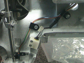
Figure 7 - Sensor Cable Routing
10. Run the cable through the access hole and into the right wiring channel, and loop the cable back around under the thread tree base (as shown in Figure 7-please note that some parts have been removed for illustration purposes).
11. Connect the cable to the four pin connector on the optical sensor PCB mounted above the thread feeder stepper motor.
12. Replace all the cable holders and cable ties.

Figure 8 - Color Change Home Flag
(Part of the upper arm front covers)
13. Align the sensor so it is centered on and does not touch the index flag as shown above and tighten the screw just enough to hold the sensor securely. Do not over tighten the screw.
14. Reinstall the right upper arm front cover. Do not move the needlecase or turn the machine off and on until this cover is reinstalled.
15. Color change to both sides of the needlecase and observe the alignment of the sensors to the flag. STOP if any adjustment is needed and make the required adjustments before proceeding.
![]()