![]()
The x/y home harness (rainbow colored ribbon cable) connects the x/y home PCB to the Main PCB at connector location J3.
Replacement Parts Needed:
harness, x/y home
twist-lock cable ties (available at most hardware stores in the electrical section)
Replacement Procedures:
1. Turn the machine OFF.
2. Remove the left transparent arm cover and the back screw of the right one.
|
|
CAUTION!! Use extreme care not to drop metallic objects, tools, or other conductive material on the Main PCB when you have the base cover removed. If you drop such objects on the Main PCB, it can severely damage the electronics which will be very expensive to repair. |
3. Remove the upper arm back cover, the base cover and the lower arm rear cover.
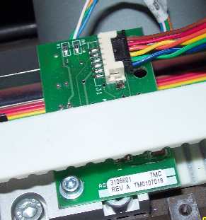
Figure 1 - Connection at X/Y Home PCB
4. Disconnect the x/y home harness from the x/y home PCB (mounted to the left y-belt clamp).
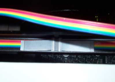
Figure 2 - Retaining Clip in Channel of Y-Home Flag
5. Gently pry the retaining clip out of the channel in the y-home flag, being careful not to damage the x/y home harness any further.

Figure 3 - X/Y Home Harness Access Hole
6. Remove the x/y home harness from the y-home flag channel and pull it through the 1/2 inch diameter access hole in the casting right above the y-home flag channel.
7. Pull the harness down to the left lower arm access hole to the main PCB, removing any twist-lock cable ties that tie it to the adjacent harnesses.
|
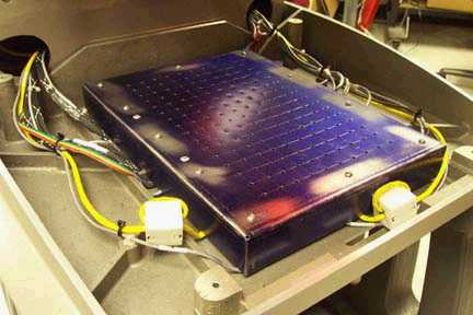
Figure 4a - 32188 Series EMI Cover |
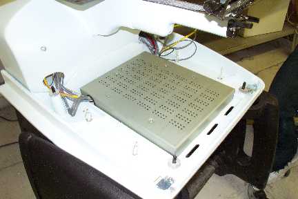
Figure 4b - 32232 Series EMI Cover |
8. Remove the EMI cover from the main control board by removing the screws from the edge of the cover.
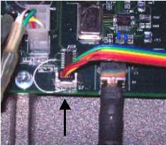
Figure 5 - X/Y Harness Connected at Main PCB (J3)
9. Disconnect the harness from the Main PCB at connector location J3.
10. Connect the replacement harness to the connector socket on the main PCB at connector location J3. This harness is assembled backwards to the other harnesses in that the extra slack is at the sensor end, instead of in the base assembly.
11. Run the harness around the left perimeter of the base interior and out the left access hole. Replace a twist-lock cable tie to bundle all the harnesses together in front of the access hole.
12. Follow the adjacent harnesses running up to the z-motor and tie the x/y home harness to the adjacent harnesses in 3-4 inch intervals up to where it runs under the z-motor.
13. Run the harness flat and neat down the channel in the y home flag and connect the harness to the y home flag. If there is a twist, correct it all the way to the z-motor so that no twist of the harness is in the length from the z-motor area to the PCB.
14. Replace the EMI cover carefully following the procedures provided in "EMI Cover - 32232 Series" or "EMI Cover - 32188 Series" as appropriate (see Figures 4a and 4b for pictures).
15. Reinstall the remaining covers in the reverse order that you removed them and tighten the screws to Melco Torque Specifications.
16. Turn the machine ON.
17. If there is any problem with the harness, you will have received an error as soon as the machine initialized because it won't find home. No further testing is required.
![]()