![]()
The thread break harness connects the thread break sensor PCB to the Main PCB at connector socket J29.
Replacement Parts Needed:
harness, thread break
twist-lock cable ties (available at most hardware stores in the electrical section)
Replacement Procedures:
2. Remove the needle case access cover and the needle case cover.
3. Remove the right transparent arm cover and the back screw of the left one.
|
|
CAUTION!! Use extreme care not to drop metallic objects, tools, or other conductive material on the Main PCB when you have the base cover removed. If you drop such objects on the Main PCB, it can severely damage the electronics which will be very expensive to repair. |
4. Remove the upper arm back cover, lower arm rear cover, and base cover.

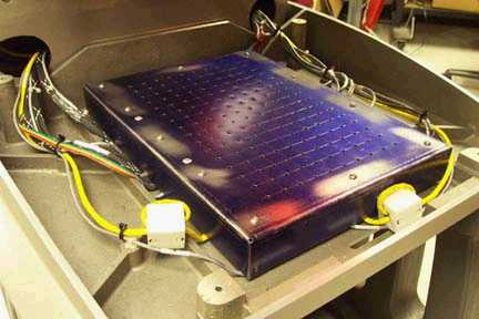
Figure 1 - Threadbreak Harness Connected to Sensor PCB
5. Disconnect the thread break harness from the thread break sensor PCB.
6. Remove all the twist-lock cable ties that tie it to the adjacent harnesses all the way up to the front of the thread tree base.
7. Remove the twist-lock cable tie that bundles the harnesses behind the thread tree base and pull the thread break harness through from the back of the thread tree base.
8. Pull the harness to the back of the machine, remove any twist-lock cable ties that bundle it to adjacent harnesses, all the way down to the right access hole to the Main PCB.
|
Figure 2a - 32188 Series EMI Cover |
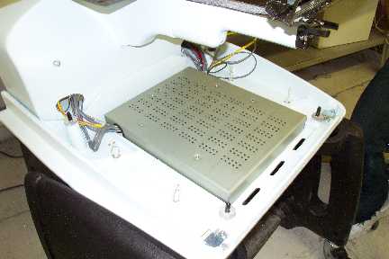
Figure 2b - 32232 Series EMI Cover |
9. Remove the EMI cover from the main control board by removing the screws from the edge of the cover.
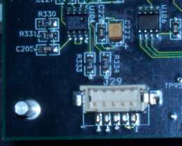
Figure 3 - Connection at Main PCB
10. Disconnect the thread break harness from the connector socket at location J29 on the Main PCB and cut any remaining cable ties bundling the thread break harness to adjacent harnesses. Remove the harness from the machine.
11. Connect the end of the thread break harness labeled "THREAD BREAK SENSOR PCB" to the connector socket on the thread break sensor PCB.
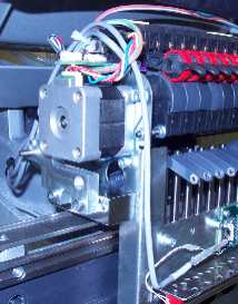
Figure 4 - Routing of Harness to Top of Needlecase
12. Run the harness to the left and then straight up and tie it at the top of the needlecase where the grabber motor harness is bundled. Pinch the harness with your finger to give it a 90° bend as shown in Figure 4 above.
13. Use a twist-lock cable tie to tie the thread break harness to the harnesses above the grabber stepper motor and run the other end of the harness under the thread tree base and pull it out from the back.
14. Use twist-lock cable ties and bundle the thread break harness to adjacent harnesses in front of the thread tree base.
15. Tie the harnesses together behind the thread tree base and route the thread break harness with the adjacent harnesses to the right into the right wiring channel and tie them together where they meet the harnesses in the channel.
16. Run the thread break harness down the wiring channel following the path of adjacent harnesses down to the Main PCB and connect it at the connector socket at location J29 on the Main PCB.
17. Replace the EMI cover carefully following the instructions provided in "EMI Cover - 32232 Series" or "EMI Cover - 32188 Series" as appropriate (see Figures 2a and 2b for pictures of the covers).
18. Reinstall the covers in the reverse order that you removed them.
19. Run a short functional test to verify that the thread break harness works. (No error message generated by the software indicating a communication break with the thread break sensor PCB.) Deliberately cut the thread where it runs into the thread feeder to see if the thread break sensor PCB detects a thread break.
20. Run the thread break sew test (AMTBTESTXXX) on the machine.
![]()