![]()
There are two led cluster harnesses connecting the LED cluster assemblies to the Main PCB at locations J9 (left harness) and J10 (right harness). The led cluster harnesses will rarely require replacement at the same time. The usual cause for replacement of either harnesses will likely be due to damage caused in handling the harnesses during repairs and/or maintenance procedures.
Replacement Parts Needed:
harness, LED cluster
twist-lock cable ties (available at most hardware stores in the electrical section)
Replacement Procedures:
1. Turn the machine ON.
3. Turn the machine OFF.
|
|
CAUTION!! Use extreme care not to drop metallic objects, tools, or other conductive material on the Main PCB when you have the base cover removed. If you drop such objects on the Main PCB, it can severely damage the electronics which will be very expensive to repair. |
4. Remove the left upper arm front cover, the right transparent arm cover, and the base cover.
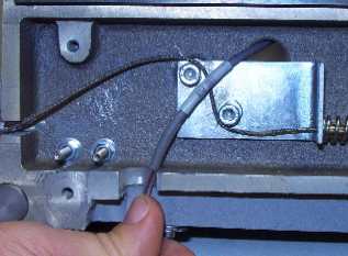
Figure 1 - Left LED Cluster Harness
5. Disconnect the LED cluster harness from the left LED cluster assembly.
6. From the back side of the left upper arm, pull the harness through the access hole located just above the x-cable tensioning bracket (Figure 1).
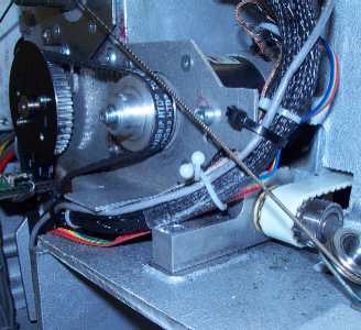
Figure 2 - LED Cluster Harness Tied to Z-Motor Mounting Bracket
7. Pull the harness through the left to the back of the machine and remove the twist-lock cable tie from the z-motor mounting bracket.
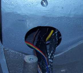
Figure 3 - Left Lower Arm Access Hole
8. Remove any twist-lock cable ties from the left LED cluster harness and pull it through the left wiring access hole in the lower arm body to the Main PCB.
|
Figure 4a - 32188 Series EMI Cover |
Figure 4b - 32232 Series EMI Cover |
9. Remove the EMI Cover from the main control board by removing the screws from the edge of the cover.
10. Remove the wire tie from the left and right LED cluster harnesses and disconnect the right LED cluster harness from the Main PCB at connector location J9.
11. Connect the new LED cluster harness to the left LED cluster assembly and run it through the z-motor mounting bracket and use a twist-lock cable tie to tie it with the adjacent harnesses to the z-motor mounting bracket (Figure 2).
12. Run the LED cluster harness following the adjacent harnesses down to and through the left lower arm access hole (Figure 3).
13. Run the LED cluster harness through the left lower arm access hole to around the left inside perimeter of the base and connect it to the Main PCB at connector location J9.
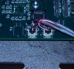
Figure 5 - LED Cluster Harnesses Connected at Main PCB
14. Place the LED cluster harnesses at the main PCB as shown in Figure 5 above.
15. Install the left upper arm front cover and tighten the screws to Melco Torque Specifications.
16. Replace the EMI cover carefully following the instructions provided in "EMI Cover - 32232 Series" or "EMI Cover - 32188 Series" as appropriate (see Figures 4a and 4b for pictures of the covers).
176. Install the remaining covers in the reverse order that you removed them and tighten the screws to Melco Torque Specifications.
18. Turn the machine ON and verify that the LEDs come on in the left LED cluster assembly.
1. Turn the machine ON.
3. Turn the machine OFF.
|
|
CAUTION!! Use extreme care not to drop metallic objects, tools, or other conductive material on the Main PCB when you have the base cover removed. If you drop such objects on the Main PCB, it can severely damaged the electronics which will be very expensive to repair. |
4. Remove the right upper arm front cover, right upper arm transparent cover and the base cover.
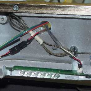
Figure 6 - Right LED Cluster Harness
5. Disconnect the LED cluster harness from the left LED cluster assembly.
6. From the back side of the right upper arm, pull the harness through the access hole located just above the x-cable clamp (Figure 5).
7. Pull the harness through the right access hole to the back of the machine, removing any twist-lock cable ties that tie it to the adjacent harnesses and pull it through the right lower arm access hole.
|
Figure 7a - 32188 Series EMI Cover |
Figure 7b - 32232 Series EMI Cover |
8. Remove the EMI Cover from the main control board by removing the screws from the edge of the cover.
9. Remove the right LED cluster harness from adjacent harnesses and disconnect the right LED cluster harness from the Main PCB at connector location J10.
10. Connect the new LED cluster harness to the right LED cluster assembly and run it the right upper arm access hole to the back of the machine to the right lower arm access hole.
11. Run the LED cluster harness through the right lower arm access hole to around the left inside perimeter of the base and connect it to the Main PCB at connector location J10.
Figure 8 - LED Cluster Harnesses Connected at Main PCB
12. Replace all twist-lock cable ties that were removed from the harnesses.
13. Replace the EMI cover carefully following the instructions provided in "EMI Cover - 32232 Series" or "EMI Cover - 32188 Series" as appropriate (see Figures 7a and 7b for pictures of the covers).
14. Install the right upper arm front cover and tighten the screws to Melco Torque Specifications.
15. Install the remaining covers in the reverse order that you removed them and tighten the screws to Melco Torque Specifications.
16. Turn the machine ON and verify that the LEDs come on in the right LED cluster assembly.
![]()