![]()
|
|
WARNING!! This procedure is intended to be performed only by specially trained Melco service technicians and personnel. Disassembly by untrained individuals will void any warranty protection and can result in personal injury or damage to the machine.
|
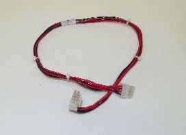
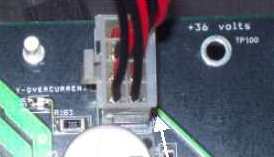
Figure 1 - 36v Power Harness
The 36v power harness connects the Main PCB (from connector location J22) to the 9-position white connector located on top of the power input assembly plate (above the power switch). The power harness will generally require replacement if it is damaged through handling, human error, or if for some reason it should get overloaded and the wire insulation begins to melt. The pins might wear out over time if the harness is disconnected and reconnected frequently. The most likely cause of damage will probably be through human error during maintenance and repair procedures.
Replacement Part Needed:
harness, 36v power
Replacement Procedure:
|
|
WARNING!! Do not attempt to repair a damaged 36V power harness if the wiring insulation is damaged through chaffing, nicks or cuts, or if the wires were overheated due to an overcurrent machine error. Never handle the 36V power harness unless power to the machine is completely disconnected. Do not rely on the power switch to break the power supply to the machine.
|
|
|
NOTE: If the 36V power harness is replaced due to an overcurrent machine error, inspect the main PCB for visible and obvious damage. It might also require replacement. |
1. Turn the machine OFF and disconnect the AC wallpower supply harness from the wall power supply outlet.
|
|
CAUTION!! Use extreme care not to drop metallic objects, tools, or other conductive material on the Main PCB when you have the base cover removed. If you drop such objects on the Main PCB, it can severely damage the electronics which will be very expensive to repair. |
2. Remove the base cover.
3. Remove the EMI cover by removing the screws on the sides.
4. Remove the lower arm rear cover.
5. Remove any twist-lock cable ties that bundle the 36V harness to adjacent harnesses.
6. Disconnect the harness connector from J22 on the Main PCB.
7. Pull the 36V power harness through the right lower arm access hole and disconnect it from the power supply input bracket.
|
Figure 1 - 36v Power Harness Connection at CPB |
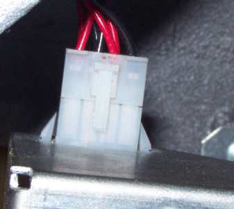
Figure 2 - 36v Power Harness at Switch |
8. Connect the replacement harness 9-position connector to the 9-position socket located above the power input switch on the power input assembly plate and run it through the right lower arm access hole and connect the other end to the 8-position header at location J22 on the main PCB. The connector will fit only in the correct direction.
9. Install the lower arm rear cover and tighten the screws to Melco Torque Specifications.
|
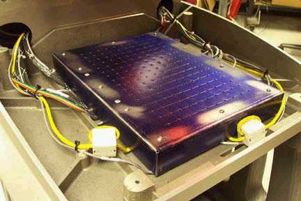
Figure 2a - 32188 Series EMI Cover |
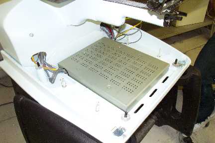
Figure 4b - 32232 Series EMI Cover |
10. Carefully replace the EMI cover following the procedures provided in "EMI Cover - 32188 Series" or "EMI Cover - 32232 Series" (see Figures 2a and 2b above for pictures).
11. Install the base cover.
![]()